The relationship between the applied strain energy release rate and the increase of damage in the cohesive zone needs a general method to calculate the value of the strain energy release rate as a function of crack length. The most common methods for the strain energy release rate evaluation by using the FEA are the contour integral (J) and the VCCT. These two methods are usually available in finite element softwares, but VCCT is intended in general as alternative to using cohesive elements while the software used in this work
(Abaqus® v. 6.11) does not output the contour integral for an integration path including cohesive element.
 |
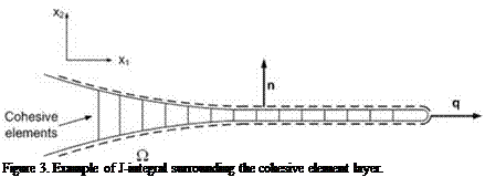
In order to compute the J-integral, a path surrounding the crack has to be selected.
Considering for example the crack in Figure 3, the path (O) is displayed by the dashed line and it is represented by the top and bottom nodes of the cohesive elements.
The J-integral definition [22] is
J = J n •[H ]• q^Q (16)
Q
where n is a vector normal to the path, q is a vector lying on the crack propagation direction, and [H] is defined as
where W is the strain energy density, the stress matrix and ui the displacements of the points lying on the path.
Neglecting geometrical nonlinearity, the vector q can be assumed to be perpendicular to the direction x2 along the whole path, therefore the J-integral can be rewritten as:
 |
Extracting the opening/sliding and the stresses in the cohesive elements at the beginning of the increment, the strain energy release rate is then computed. An interesting feature of this approach is that the mode I and the mode II component of the J-integral can be obtained by integrating separately the second or the first components of the integral in Eq.(18), respectively.
This method can be easily implemented for a two-dimensional problem, since there is only one possible path. In the case of three dimensional problems, the implementation is more difficult since several paths can be identified along the crack width, and moreover their definition is rather troublesome, especially when dealing with irregular meshes. In this work, a three-dimensional version has been implemented for the case of planar crack geometries and regular cohesive mesh, for which Eq.(18) is evaluated on several parallel contours in order to obtain J-integral along the crack front.
 9 января, 2016
  Pokraskin
  Опубликовано в рубрике