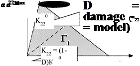
Although, different and complicated shapes of the cohesive law are proposed in the literature, the triangular one (Figure 1) is taken as it is often
good enough to describe crack growth behaviour. In that case, damage starts once the tripping stress Symax has been attained, decreasing progressively the element stiffness Kij.
 |
damage initiation
Figure 1. Example of a triangular cohesive law.
However, the model “as is” does not incorporate subcritical damage accumulation, i. e., cyclic damage is not possible below аі]0 and does not accumulate beyond the first cycle above. In this model, the concept proposed in [12] is retained, while fundamental differences with respect to that work concern: i) the damage D is related directly to its effect on stiffness and not to the ratio between the energy dissipated during the damage process and the cohesive energy and then, in turn, to the stiffness; ii) the process zone size ACZ is defined as the sum of Ae of the cohesive elements for which the difference in opening between the maximum and minimum load of the fatigue
![]() AS = S
AS = S
cycle,
it is evaluated by FEA during the simulation and not derived from a theoretical model; iii) the strain energy release rate is calculated using the contour integral method over the cohesive process zone and it is implemented as a user-defined field subroutine (USDFLD) in Abaqus acting on standard cohesive elements, instead of a user element.
Considering a Representative Surface Element (represented in the simulation by a the cohesive element section pertaining to one integration point, Figure 2) with a nominal surface equal to Ae, the accumulated damage can be related to the damaged area due to micro voids or crack (Ad):
![]()
|
|
|
|
|
|
|
|
In [12], D is related to the ratio between the energy dissipated during the damage process and the cohesive energy (Г22 in Figure 1) and then, in turn, to the stiffness. In the present model instead, D acts directly on stiffness, alike in [20].
|
Referring to a mode I loading case, when the opening is relatively small the cohesive element behaves linearly; this happens until a given value of displacement, d220 (or equivalently until a certain value of stress a220). This initial step is characterized by a stiffness K220, that remains constant until d22,0. Beyond this limit the stiffness is progressively reduced by D, until the final fracture in S22,c where the two surfaces are completely separated. Between S22,0 and S22, C the stiffness K22 can be computed as
K22 = K22,0 (1 — D) (3)
The area Г22 underling the cohesive law is the energy to make the defect grow of a unit area and it is therefore representative of the fracture toughness,
Gic.
C
Г22 _ j^22d^22
0
 |
|
In the monotonic case, the damage variable D can be written as a function of the opening (622) and of the damage initiation and critical opening (respectively 622,0 and 622,0 ):
When the element is unloaded, the damage cannot be healed, therefore, looking at Figure 1, the unloading and subsequent loadings will follow the dashed line, until a further damage is attained. This simple model is able to describe the monotonic damage in case of mode I loading.
Considering the entire cohesive layer, the areal crack extension (A) can be computed as the sum of damaged areas of all the cohesive elements integration points (Ad) [12]
A = X Ad (6)
When the fatigue damage is considered, from the previous equation, the crack growth (dA ) can be written as a function of the increment of the damage area of all the cohesive elements (dAd), therefore:
dA = Z dAd (7)
However the damage increment would not concern the whole cohesive layer, but it will be concentrated in a relatively small process zone close to the crack tip. In order to estimate the size of ACZ, analytical relationships can be found in the literature [21], where the size per unit thickness is defined as the distance from the crack tip to the point where o22,0 is attained. In this work, a different definition and evaluation method is proposed: ACZ corresponds to the sum of the nominal sections of the cohesive elements where the difference in opening between the maximum and minimum load of the fatigue cycle,
A^ = 8^ — A22,mn, is higher than a threshold value A^22 . The value
is supposed to be the highest value of in the cohesive layer when AG in the simulation equals AGth experimentally obtained by FCG tests. It has to be
underlined that in this way FCG may take place even at A22,max < c>22,0 ,
which is a condition that should be accounted for since S22,o results from the calibration of cohesive zone on fracture tests and may not be representative of a threshold for FCG. The process zone size ACZ has therefore to be evaluated by FEA while performing the FCG simulation but, on the other hand, does not need to be assumed from a theoretical model.
Eq.(7) can be therefore rewritten as [12]
dA = £ dAj (8)
ieACZ
where only the elements lying in the process zone (namely ACZ) are considered.
In order to represent the crack growth due to fatigue (dA/dN), the local damage of the cohesive elements (D) has to be related to the number of cycles (N). This is done using the equation
—- =————— (9)
The first part of Eq. (9) can be easily obtained deriving Eq. (2): therefore
![]() dD _ 1 dAd ~ Ae
dD _ 1 dAd ~ Ae
The process to obtain the second part is quite more complicated: the derivative of Eq.(8) with respect to the number of cycles is
At this point an assumption is introduced: the increment of damage per cycle is supposed to be the same for all the elements lying in the process zone. Therefore the value dAd/dN is assumed to be the average value of the damaged area growth rate dAj/dN for all of the elements in the process zone.
Hence the crack growth rate can be rewritten as [12]:
![]() dA _ у dAd dAd
dA _ у dAd dAd
dN dN cz dN where ncz is the number of elements lying on the process area Acz. ncz can be written as the ratio between the process zone extension (Acz) and the nominal cross section area (Ae) leading to the equation
![]()
![]() dA _ Acz dAd dN ~ A dN
dA _ Acz dAd dN ~ A dN
The second part of Eq. (9) can be therefore written as:
Combining Eqs. (10) and (14), the crack growth rate can be finally expressed as a function of the applied strain energy release rate, in the simplest version using Eq.(1)
— = — BAGd (15)
dN Acz
 8 января, 2016
  Pokraskin
 Опубликовано в рубрике