Nowadays steel wheels and aluminum alloy wheels own about 50 % of the market share. Often aluminum alloy wheels are preferred for their thin-spoke appearance, but in a field dominated by the constant request of weight and consumption reduction, the automakers more frequently opt for steel wheels to trim the weight of their products as they are lighter and much more cost effective than their aluminum equivalent (American Iron and Steel Institute, 2004; Crain Communications, 2013; M. W. Italia SpA, n. d.).
The current steel wheel is composed of two components, the disc and the rim, joined together by force fitting one into the other and then welded, as schematized in figure 12. Welding is a classic method to join steel components together, but often it is not possible to weld two different metals or joining metals to ceramic, composite or polymeric materials. The exploitation of new
 |
|
 |
|
materials and new metal alloys is a key solution for obtaining lightweight structures and more innovative and attractive products, with the consequent requirement of a revision of the joining technology.
Figure 12.Schematic representation of the present joining technology of the wheel system.
 |
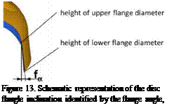
The presence of the interference fit in the wheel is necessary for structural purposes. The introduction of an adhesive instead of the welding in the interference-fit system can lead to an interference fitted-adhesive bonded hybrid joint in the wheel. The wheel has a relatively complex design, where many variables can affect its structural behavior. For instance, the disc flange is not straight, but it is characterized by an inclination. The extent of this inclination is indicated by the flange angle, fa, and generates different interference levels: a lower interference at the level of the upper flange diameter, UFD; a stronger interference at the level of the lower flange diameter, LFD, as depicted in figure 13. The not univocal interference level plus the plastic deformations of the rim during the press-fit generate a radial contact pressure along the joint area that is not constant and difficult to estimate.
Preliminary static tests were carried out on bonded wheel prototypes in order to understand their general structural resistance and to evaluate the
interaction between the adhesive and the interference level in the wheel system. A passenger car wheel was used. In order to create various levels of fitting force, rims were produced with different diameters. The normal production discs were coupled with the different rims obtaining three separate interference classes: stronger interference (A), lower interference (B), transition fit (C). All the interferences and diameters of the sample classes are collected in table 3.
|
Table 3. Diameters and interferences of the A, B and C classes
|
 5 октября, 2015
  Pokraskin
  Опубликовано в рубрике