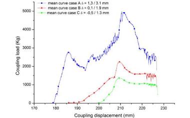
The coupling load/displacement curves of the bonded wheels were collected during press-fitting. The mean curves of five samples for each case (A, B and C) are reported in figure 14.
|
Figure 14. Comparison among the mean coupling curves of bonded wheels for the different fitting-force cases. |
All the samples were assembled by using the same discs having the same flange angle. Thus, two interference levels were calculated for the UFD and the LFD, as reported in table 3. The peak of the entrance of the thinner upper part of the disc flange was visible at 185 mm only for the case A. The peak was very smooth in the case B, corresponding to an interference level at the UFD practically inexistent (0.1 mm). For what concern the case C, a clearance was present between the upper part of the flange and the rim well, thus no load was recorded at this displacement. On the other hand, the peak at 210 mm was due to the entrance in the rim well of the larger end of the disc flange. Indeed, it increased from case C to case A according to the interference levels at the LFD.
 6 октября, 2015
  Pokraskin
 Опубликовано в рубрике