The spray application of internal lacquers has many disadvantages with non-uniform distribution of the lacquer being a major factor. Due to the non-uniformity of the film a thicker than required film is applied over most of the can to ensure that the area where the film will be lowest in weight is sufficient to protect the can and its contents. Too high a film weight in other areas may cause blistering. It will certainly increase the cost per coated can. Theoretically, electrodeposition overcomes this problem and there have been numerous attempts to commercialise this process which works successfully when a few large objects are coated per minute, as in a car production line, but is fraught with problems when 1500 to 2000 small objects need to be coated every minute of every hour. The mechanical (and electromechanical) handling of the cans poses problems which are currently considered to be insurmountable.
The concept of electrocoating cans is not new, in fact it was mentioned as long ago as 1936(20). However, Metal Box pioneered the development of sophisticated equipment which could have made the concept a commercial reality(21). In practice, the Metal Box electrodeposition system failed because of the problems of short circuits when the electrodes were inserted into the cans at the speeds required to enable economic can production. This development was complemented by the development of lacquer systems tailored for application by electrodeposition.
 |
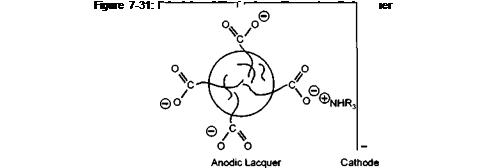
To illustrate the principle, Figure 7-31 shows a micelle particle with its charge bearing stabilising groups, between two electrodes of an electric cell. The negatively charged particle will be attracted to the positively charged anode. The positively charged neutralising amine will be attracted to the cathode. At the anode the carboxylic anion will be protonated and with the loss of its ionic character, it will also lose its ability to stabilise the particle in aqueous media. The destabilised particles will precipitate onto the anode surface as a film.
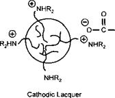
This is a model of an anodic electrocoat lacquer. If the positively charged amine groups are built into the polymer, and low molecular weight carboxylic acids are used as the neutralising species, then the polymer particle would deposit on the cathode as shown in Figure 7-32. Cathodic systems are well known in the automotive electrocoat field and have been progressively replacing anodic systems in the last fifteen years. This is because the iron may be dissolved into the lacquer during anodic deposition. This does not occur during cathodic deposition because the iron is deposited onto the metal. In can coatings most systems are anodic. The single most important reason for this, when tinplate is the substrate to be coated, is the difficulty in formulating FDA approvable cathodic lacquers, particularly at costs competetive to anodic lacquers. When aluminium is the substrate, anodic systems are the natural choice, as the aluminium anode will be anodised and passivated during the electrocoating operation.
+
![]()
 Anode
Anode
Figure 7-32: Principle of Electrodeposition — Cathodic Lacquer
The surge of interest in electrocoating cans has meant that the polymer chemist has had to learn how to formulate lacquers to meet a new set of parameters. Important factors in spray application such as low weight coverage, blister threshold and reverse wall failures no longer applied. The correctly formulated electrocoat lacquer deposits a uniform film over the can surface and is thrown onto the most difficult surfaces, like the reverse wall or beaded side wall, which may be in the shadow of the spray pattern from a spray gun fixed at the mouth of the can. Some of the important parameters in electrocoat are:
• Rupture voltage
• Throwing power
• Rinse sensitivity.
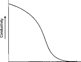
During deposition of the film the surface exposed to the electrodeposition changes in restivity. The bare metal is highly conductive. When the coating starts to deposit this conductivity is reduced until at the limit the film is insulating. This can be illustrated in Figure 7-33.
|
Film Thickness |
Figure 7-33: Conductivity Versus Film Thickness
When the charged particles are no longer attracted to the surface in a particular area, because its resistivity has increased, the particle may move to an adjacent area which is un — or partially coated. The ability to move away from the electrode and penetrate into spaces where the electrode cannot penetrate is termed throwing power. The greater the movement of the coating from the electrode, the greater the throwing power of the lacquer. In the Metal Box designed cell the electrode was inserted into the can. Whilst this minimised the throwing power required from the lacquer, it was the major cause of the short circuits, eventually causing the project to be abandoned.
It is well known that factors which effect the resistivity of the green (unstoved) film will affect throwing power. In terms of lacquer formulation, it is possible to improve throwing power by making the polymer more hydrophobic, e. g. decreasing the water solubility of the polymer backbone by attaching hydrophobic side chains.
Rupture voltage is another important parameter. After depositing a film that has sufficient resistance to stop the flow of electricity, no more deposition can take place. Film weight is controlled by adjusting the voltage. If, however, the coating is not correctly formulated, it is possible for the resistance of the green film to be broken by the voltage that is being applied. In this case, the film will rupture and further deposition will take place. The rupture voltage of the green film must be well above the voltages that are to be used to deposit film weights in the desired range.
One of the important design parameters affecting rupture voltage is the correct choice of type and level of co-solvent. Another factor is the degree of neutralisation, with higher amine levels giving lower rupture voltages.
Having successfully deposited a green film, the coating is then rinsed to remove residual coating from the can before stoving. Obviously, the green film must not be redissolved in the rinse and washed off. For example, if polymers with too high an acid value are used, they will remain water sensitive. Also the right balance of water miscible and immiscible co-solvents in the deposited green film will affect water sensitivity and appearance after rinsing.
During the deposition of the coating, water is excluded ( at least partially ) from the film. If it were not then the coating would remain conductive and coating would continue to be deposited. This in essence reduces the VOC of the coating. There is a bath VOC and a film VOC. Taking 20% as a typical solid content for a waterborne spray lacquer, it is possible to make comparisons of the compositions of the wet films before stoving of coatings applied by spray and by electrodeposition. Table 7-18 shows this comparison and demonstrates that the VOC of the wet film is lower with electrocoat, because the process deposits a much high sohds film than spray apphcation. Table 7-18 shows the most favourable comparison possible. There are volatile organics contained in, for example, any rinse that is carried with the can into the oven which detract a little from this situation. However, there is real potential for getting very low organic emissions out of an electrocoat system.
|
TABLE 7-18: COMPARISON OF COMPOSITION OF WET FILMS FROM SPRAY AND ELECTROCOAT APPLICATION
|
Some advantages claimed by supporters of electrocoat for internal lacquer application are given in Table 7-19. Many are self explanatory, however, some will be explained further
 |
The uniform coverage is theoretical. The distribution should be more uniform than that from internal spray but it will not be 1:1:1:USW:MSW:LSW (upper side walbmid side wall dower side wall). This way of expressing distribution is not uncommon in the industry.
There are many claims about how much film weights can be reduced because of the uniformity of films deposited by electrocoat. Some of these claims appear to many to be over optimistic and some may even verge on being fanciful. Whether steel cans can only have a single coat is debatable, but it has been shown that one coat, when electrodeposited onto steel cans, will give acceptable performance, under laboratory and pilot scale conditions. What is for certain is that electrocoat can only be used for one coat of lacquer. Once the can is coated, no further coating can be deposited by electrodeposition. A second coat would need to be spray applied which could be considered counter productive. However, if a sufficiently thick and, more importantly, integral film free from defects could be uniformly deposited onto a steel can, then one coat application is feasible. This will require joint efforts from equipment manufacturers, lacquer suppliers and can makers.
Because the application is by movement of particles under an external electrical influence, line of sight necessary for airless spraying is not required for electrodeposition. The possibilities of post lacquering complex shaped cars are opened up.
Depending upon the stage of application of the electrocoat, it is possible to coat simultaneously internally and externally. This, however, dictates that the lacquer is applied before any other coating, which is the opposite of the current practice of applying the internal lacquer after all other coating and inking operations have been completed.
The lacquer will electrocoat all uncoated metal immersed in the electrodeposition bath. It should be borne in mind that there will always be at least one area, however, small, of the can which will be uncoated. This is the point or points where electrical contact is made which enables the can to act as an electrode. This is always on the external surface. No uncoated metal must be allowed to come into contact with the contents of the can. In most cases it would be anticipated that the internal lacquer would be applied last, thus the lacquer must not adhere, damage, stain or detract from the appearance of the external decoration. It is feasible that steel cans could have an internal and external lacquer electrodeposited in the first coating operation and use a spray applied internal lacquer as the last operation. In this case, the electrocoated internal lacquer must have the characteristics of the external lacquer, particularly mobility, if a novar system is used.
The use of electricity to coat the can opens up the possibilities of electrically checking the integrity of the internal coating of each and every can. This has long been a can maker’s dream and goal, due to the anticipated reduced claims and spoilage of packed products. However, this checking would need a separate operation and it is arguable whether existing can lines could incorporate a similar approach with existing spray applied internal lacquers.
These advantages offer major advantages to companies who can be successful with this technology. Thus, it is of no surprise that further attempts have been made to develop alternative electrocoat technologies since the disappointing failure of the Metal Box system. The latest approach seems to overcome many of the problems associated with inserting electrodes into cans at up to 1500 cans per minute. Gutec technology has been licensed by Cincinnati Industrial Machinery USA. Full details will not be given here, but can be obtained from them(22). An electrodeposition bath is still used, but pumps cause liquid to be moved upwards, not unlike can washing. This liquid is charged and so is the can. The can is virtually immersed in the bath. Coating is by a combination of chemical and physical factors. Presenting and removing the number of cans for economic coating still presents a problem in this technology. Trials have been undertaken and further developments are anticipated.
Electrodeposition onto coil is much easier in the sense that the coil can be electrically charged at the ‘unwind’ end of the coil. The coil passes through the bath, with the bath length and coil speed determining the residence time. It is believed that there is one coil line in North America using electrodeposition for coating DWI easy open ends. This coating must be waterbased and probably contains some degree of functionality. It is also believed that there is a semi pilot scale DWI internal lacquer electrodeposition line running successfully in mainland Europe. The types of resins covered in these coatings are considered in more detail in the Epoxy book in this series.
 13 октября, 2015
  Malyar
 Опубликовано в рубрике