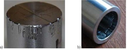
Unbonded interference-fit samples were prepared by using the press-fitted hub/shaft joints and tested in static axial pull-out in order to understand the strength contribution of the interference-fit alone (Gallio et al., 2014). Assuming the same friction coefficient between steel and steel for all the samples, a linear relationship between the interference and the pull-out force according to the theoretical equation (eq.1) should be expected at the experimental level. Nevertheless, the experimental results related to the unbonded joints were affected by a wide variability of the results. The ideal system described by the equation did not consider the phenomena of wear and micro-adhesion that took place in the samples between the two steel components, as illustrated in figure 3 for both the sliding bodies.
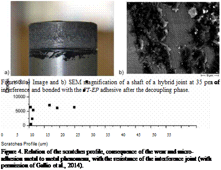
In order to quantify the extent of the wear on the decoupled samples, their surface was analyzed by means of a profilometer. By subtracting the measured real profile to the averaged ideal one, an absolute value of discrepancy was obtained. This discrepancy parameter was labeled as “scratch profile” and it indicates the extent of the wear phenomena (Gallio et al., 2014).
The importance of the wear and micro-adhesion phenomena on the resistance of the unbonded joints could be appreciated by plotting the measured pull-out loads as a function of the scratches profile values (Figure 4) (Gallio et al., 2014).
It can be noted that the extent of the damage caused by wear phenomena was higher in the unbonded interference samples that showed stronger resistance to the decoupling. In fact, when a metallic junction is formed between two sliding surfaces made of the same metal, the wear phenomena including processes of deformation, local adhesion and welding can appreciably increase its shear-strength (Bowden & Tabor, 1950).
Because of this phenomena, it was not possible to detect the interference contribution by the unbonded interference joints.
|
Figure 3. Sample at high interference level characterized by large surface damages after the decoupling: a) shaft and b) hub (with permission of Gallio et al., 2014). |
 |
Differently, no scratches and wear were present in the case of the hybrid joints after the decoupling, being their mating area covered by a thin layer of adhesive, as illustrated in figure 5. During the coupling operation, the adhesive, still liquid, acts as a lubricant preventing friction effects. During the decoupling, the cured adhesive avoids the direct metal-metal contact and consequently the formation of scratches (Gallio et al., 2014).
 The fracture surfaces of hubs and shafts were observed and a section of the bonded area of the shaft for each sample was analyzed at the Scanning Electron Microscope (SEM). Very few differences were observed between samples bonded with the FT-EP at different interference levels: it was difficult to detect a clear adhesive or cohesive failure modes as residues of the adhesive layer were present on both the mating surfaces.
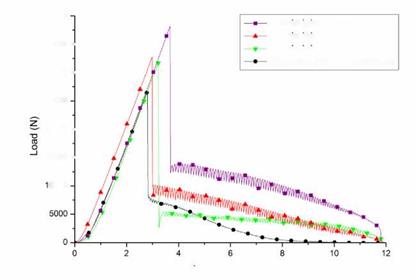
The decoupling curves of the hybrid samples prepared with the FT-EP adhesive were characterized by two main phases: an initial load peak and a following additional load with a stick/slip trend. The initial peak was due to the contribution of the adhesive plus the interference. The adhesive break up point occurred in correspondence with the maximum of the peak. After the adhesive failure, in order to complete the decoupling, an additional load is necessary to exceed the interference contribution.
The hybrid joint samples with three different classes of interference (10, 22,5 and 35 цт) provided three different additional loads after the break up of the adhesive. Some examples of load-displacement curves related to the decoupling of hybrid joints at different interference levels and of an adhesive joint in clearance condition are shown in figure 6 (Gallio et al., 2014).
40000
30000 — 25000 20000 — 15000- 0000
Displacement (mm)
Figure 6. Decoupling curves of three hybrid joints at different interferences and an adhesive joint in clearance condition. At least 4 samples for each class of interference were tested, only one sample is shown as an example in the graph (with permission of Gallio et al., 2014).
The adhesive joints in clearance conditions were also characterized by a residual load level after the break up of the adhesive, due to the friction forces between the cured adhesive residues present on the fracture surfaces. This load presented a different behavior with respect to the interference residual load recorded in the hybrid joints, since it expired before the complete decoupling of the joint.
The load after break in the hybrid joints mainly depended on the radial contact pressure present between the hub and the shaft due to the interference fit. The important contribution due to the friction and wear phenomena observed in the unbonded samples was absent in these joints, thus the load after break can be most likely referred to the system described by the analytical equations. According to this hypothesis, the load after break can be more easily related to the contribution provided by the interference level. In order to obtain an estimation of this additional load, the mean value between the first peak and first valley of the stick and slip state was calculated. The obtained values are plotted in figure 7 and compared to those of the unbonded interference samples.
![]()

 40000 —
35000 —
30000 —
25000 —
Z —
-o 20000- ro
O —
150001000050000-0
Figure 7. Comparison among the interference contribution detected from the load after break of hybrid joints, the unbonded interference samples, and the results obtained from the analytical equations.
As highlighted in figure 7, the loads after break of the hybrid joints were in good agreement with the theoretical results of Fint obtained by processing the measured dimensions of the samples with the Lame thick walled cylindrical theory and the equation 1, employing a coefficient of friction equal to 0.3 (simulating slightly lubricated surfaces) and a Modulus of the steel adherends of 190 GPa. This relation confirms the assumption of the load after break of hybrid joints as the interference contribution in these samples (Gallio et al., 2014).
 14 сентября, 2015
  Pokraskin
 Опубликовано в рубрике