Pin-collars manufactured according to ISO 10123 have a coupling diameter of about 12.65 mm. When a shrink-fit or a cryogenic-fit has to be performed, a certain radial clearance, and a sufficient assembly time shall be ensured, before the components return to their original dimensions. It is known that a linear relationship exists between the thermal deformation of a metallic body and temperature [16].
|
|
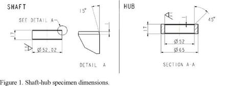
In the light of that, the relatively small dimensions of pin-collars realized as for ISO 10123 have a double drawback: they allow for small radial displacements, even under great temperature differentials, and they do have a small thermal inertia. In order to avoid assembly issues, the authors designed and realized the specimen shown in Figure 1, to be used in the presence of interference. The bigger size of such shaft-hub specimen, with respect to pin collars, allows for a greater assembly clearance and increases the time available for assembly operations. For example, referring to a nominal coupling diameter DC = 52 mm, to a radial interference I=0.01 mm, to the coefficient of thermal expansion aW=1.1 10-5 for steel, and to a R. T. of +20°C, a radial assembly clearance of g=0.07 mm is obtained when the hub is heated at +180°C for the shrink fit. Such assembly clearance permits to join the components by hand easily. As for cryogenic fits, by taking into account a coefficient of thermal contraction of aC=9.5 10-6 and a cooling temperature for the shaft of -150°C, a radial assembly clearance of g=0.06 mm is obtained, which is still acceptable. Cryogenic fits are performed by means of liquid nitrogen and the temperatures indicated above are meant at the time of coupling. The coupling length of shaft-hub specimens was defined in order to obtain a push-out force always lower than the limit of the standing press (100 kN) whatever was the coupling condition; the material type was kept unchanged with respect to the pin-collars one. Shaft — hub specimens with interference and without adhesive were used to sample the frictional contribution Fint to be used for calculating the overall release force Ftot, as for Eq. (3). A total of 34 shaft-hub specimens were realized, out of which 7 were press fitted without adhesive, 7 were press fitted with adhesive, 10 were shrink fitted with adhesive and, 10 were cryogenically fitted with adhesive. In the case of shrink fit, the adhesive was dispensed on the shaft, while in the other two cases it was dispensed on the hub. Table 2 summarizes the test plan for shaft-hub couplings. Since all shaft-hub couplings were assembled with interference, the adhesive shear strength has to be calculated according to Eq. (3).
|
Table 2. Test plan for shaft-hub specimens, tested with interference, single run
|
 4 сентября, 2015
  Pokraskin
 Опубликовано в рубрике