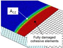
The 3D model performance is compared with the 2D version [19] concerning the value of G as a function of crack length. Due to crack front bowing (Figure 7), the average G (or Gj, Gjj) and crack length along the crack front were considered for the comparison with the 2D model. In the case of elastic, isotropic material parts, analytical solutions for G (Mode I [29], Mode II [30] and Mixed/Mode I/II [31]) were also introduced in the comparison, while in the case of the elastic, orthotropic composite the value of G obtained by quasi-static FE simulation using VCCT were considered.
Additionally, Eq.(1) is integrated numerically using the G vs. crack length coming from the analysis instead of taking directly the output number of cycles. The reason is that, as the CZM process zone needs some time to get to a steady state, the G calculated by CZM may be rather different from the analytical one in the first millimeters of propagation yielding a different number of cycles. For this reason, a comparison with experiments is foreseen as a further validation step, while at the moment the paper focuses on the comparison of numerical results of the present model and analytical solution after the transient phase of process zone formation.
|
Figure 7. Bowed crack front and process zone in mode I fatigue modeling. |
 18 января, 2016
  Pokraskin
 Опубликовано в рубрике