In order to test the behavior of different adhesive systems in the hybrid joint and to analyze the influence of the interference contribution, hub/shaft laboratory samples were created.
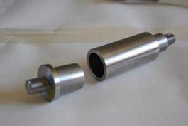
The hollow tubes and the shafts were designed according to the requirements imposed by our traction and fatigue test machines. The laboratory samples were machined in C40 steel, the nominal coupling diameter of the samples was set to 30 mm and the coupling length was fixed to 10 mm (Gallio et al., 2014, 2013). A picture of the components is reported in figure 1 (Gallio et al., 2013).
|
Figure 1. A hub and a shaft (with permission of Gallio et al., 2013). |
Generally, the two cylindrical components could be assembled through two principal methods: the shrink-fit and the press-fit. In the case of the shrink-fit, the preferred approach is to apply the adhesive to the male component and to heat the female to obtain the needed fitting clearance. In the case of the press-fit assembling technique, the adhesive is generally applied as a film to one or both substrates and the parts are coupled by means of a standing press with possible problems concerning misalignments and the splitting away fo the adhesives (Croccolo et al., 2013; Kleiner & Fleischmann, 2011).
In our experiments, the hub/shaft joints were assembled according to the press-fit method. The alignment between the shaft and the hub was a crucial parameter to obtain repeatable joints. A not-axial assembling induces far higher coupling and decoupling loads than an axial one. A method of guides was then exploited to guarantee the alignment of the couples (more information can be found in previous papers (Gallio et al., 2014, 2013)). The pressing was performed by means of an automatic press in order to assure the same pressing rate for each sample. During the press coupling operation, the samples (both hub and shaft) were not fastened but self-arranged into the guides. The alignment was confirmed by putting in rotation the assembled joints and measuring the eccentricity between the hub and the shaft.
The joint geometry of our samples surely implied the presence of spew fillets, being the shaft press-fitted into the hub. The external spew fillet was visible after the coupling and it was removed before the adhesive cure. The internal one was observed after the breaking of the joint, but the geometry of the sample made impossible to remove it. Indeed, according to the pin and collar test method, a cord shaped adhesive spew must remain in one of the collar ends (Abenojar et al., 2013).
In order to evaluate the performances of the interference fitted-adhesive bonded joints, the samples were tested under an axial pull-out load.
The traction test was carried out at a crosshead speed of 1.3 mm/min. Considering that no standards are available for the hybrid interference fitted joint, the crosshead speed was selected on the basis of the low load rate generally suggested in the standard shear tests on adhesive joints, in particular referring to the load provided per unit area per second (Abenojar et al., 2013; Astm D1002-01, 2001; Astm D5656-01, 2001).
Two sets of experiments were carried out separately on different test machines. The first was related to test different adhesives in the interference fit system (Gallio et al., 2013). In this experimental part, the interference was set to a coupling condition of H7/p6 according to the ISO system of tolerances (ISO 286-1:2010, 2010). The tested adhesives belong to the adhesive families most employed for structural purposes, based on the Epoxy, Acrylic and Polyurethane systems (Comyn, 1997; Dillard, 2010; Petrie, 2007). The different adhesive families can be classified on the basis of the adhesion strength that they provide against their flexibility. Generally rigid adhesives provide high joint strengths and are selected for applications requiring high shear resistance and low peel and impact strength. On the other hand, flexible adhesives are characterized by a lower adhesion strength, but are suited for joints loaded in peel or cleavage, or in presence of components vibrations, and they usually provide a good impact resistance (Adams et al., 1997; Petrie, 2007).
The investigated adhesives were: (1) (R-EP) a 2k rigid epoxy adhesive, Hysol® 9492, with high resistance (Bulk tensile strength = 31 MPa), but low flexibility (Elongation at break = 0.8 %) (Henkel Ag & Co. KGaA., 2011); (2) (FT-EP) a 2k flexibilized and toughened epoxy adhesive, Scotch-weld® DP490, with high resistance (Shear on grit blasted steel = 28.7 MPa) and high peel resistance (Peel strength = 9,2 N/mm) (3M Company, n. d.); (3) (AC) a lk high resistant anaerobic acrylic adhesive, Loctite® 620 (Shear on steel = 17.2 MPa) (Henkel Ag & Co. KGaA., 2011); (4) (PU) a 2k modified polyurethane adhesive, Araldite® 2029, that provides characteristics of both resistance (Shear on grit blasted steel = 24 MPa) and flexibility (Elongation at break = 39 %) (Huntsman Corporation, 2013).
The design of the experiment is depicted in table 1, a minimum of 4 specimens were tested for each sample type.
|
Table 1. Design of the experiment for different adhesives in the interference fit
|
The second set of experiments was carried out to identify the interference contribution in the hub/shaft samples and its interaction in the hybrid joints bonded with the FT-EP adhesive (Gallio et al., 2014). The design of the experiment is depicted in table 2, a minimum of 4 specimens were tested for each sample type.
|
Table 2. Design of the experiment for different interference levels in the hybrid joint
|
Fatigue tests on hybrid joints bonded with the FT-EP adhesive were also carried out, by using a tension-tension fatigue test (Croccolo et al., 2010; Sekercioglu et al., 2005) on a resonant testing machine.
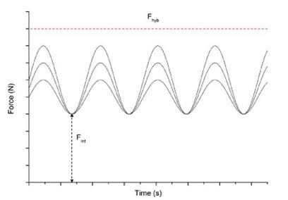
Some considerations about the tension-tension variable amplitudes employed has to be done. The minimum load amplitude was set constant for each sample, on the basis of the resistance provided by the interference contribution (Fint). The maximum amplitude was varied among different percentages of the static total resistance of the hybrid joint (Fy). Indeed, Dragoni et al. (Dragoni, 2003) showed that the strength decay of hybrid joints subjected to fatigue loading could be imputable to the adhesive contribution, meanwhile the non-bonded interface is virtually unaffected by a fatigue decay. A schematic example of the fatigue cycles performed is presented in figure 2.
|
Figure 2. Schematic example of the load cycles employed in fatigue tests. |
The load cycle frequency of the fatigue test was dependent on the typical frequency of the samples as the used fatigue machine operates in resonance frequency. The single fatigue test was considered terminated at the attainment of 106 fatigue cycles or at the joint failure (identified by a variation in the testing resonance frequency). Two specimens were tested for each investigated amplitude.
 12 сентября, 2015
  Pokraskin

 Опубликовано в рубрике