The theoretical framework described in the first section and the strain energy release rate (SERR) calculation procedures are implemented programming Fortran subroutines templates available in the commercial software Abaqus®. In particular the USDFLD Abaqus® subroutine is used to modify the cohesive element stiffness by means of a field variable that accounts for damage, while the URDFIL subroutine is used to get the result in terms of stresses, displacements and energies. The fatigue analysis is carried out a as a simple static analysis, divided in a certain number of increments. Each increment corresponds to a given number of cycles.
Assuming that the fatigue cycle load varies from a maximum value Pmax to a minimum value Pmin, the analysis is carried out applying to the model the maximum load Pmax. The load ratio is defined as the ratio between the minimum and maximum load applied
ДО = (1 — R^mx (19)
The strain energy release rate amplitude is therefore
R = (20)
Pmin
This latter is compared with the strain energy release rate threshold AGth. If AG > AGth the analysis starts (or it continues is the increment is not the first) otherwise the analysis is stopped.
Routine for the
calculation of AG, AG1
increment j __________ —
increment j
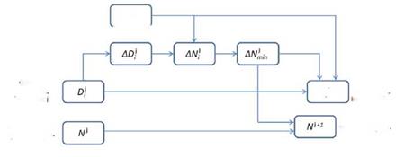
Figure 4. Flow diagram of the automatic procedure for the crack growth rate prediction.
 |
 |
|
The flow diagram in Figure 4 shows the operations done within each increment, where ADi is calculated as follows:
In other words, AD/ is the minimum between the ADmax and the amount needed for D to reach the unity. The procedure is explained in detail in [19].
It is worth to underline that the procedure is fully automated, i. e., the simulation is performed in a unique run without stops. During the initial loading ramp, the stress-strain behavior is represented by the input cohesive law and the statically accumulated damage, represented by Eq. (5), is stored for the cohesive elements where S > S0. The stiffness is then degraded according to the procedure described previously, starting from the stored static value until D = 1. If Smax of the cycle is lower than S0 but AS > ASth, elements entering the process zone during the fatigue analysis step start damaging before S > S0. In this case the stress deviates from the linear elastic region of
the cohesive law to fall on the linear damage part at 8 < 80, i. e., without reaching CTmax.
Whenever a static overload occurs at a certain point in life, the cohesive element responds elastically with a degraded stiffness K instead of K0, and further damage, or even static crack growth, can be accumulated related to the overload according to Eq. (5). After the overload, cyclic loading starts from the value of cyclic + static damage stored previously, see [23].
 16 января, 2016
  Pokraskin
 Опубликовано в рубрике