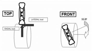
The rolling test was employed to simulate the fatigue stress that the wheel undergoes during its operating life on vehicles. In this test the wheel is placed on a roller and it is subjected to rolling cycles. The machine is able to apply a radial load and a lateral load to simulate the use on vehicles, with a constant monitoring of these parameters during the test. The loading scheme of the test is depicted in figure 18.
|
Figure 18. The loading scheme of the rolling test on wheels (M. W. Italia SpA, n. d.). |
The fatigue cycle parameters were chosen on the basis of the most harsh standard fatigue test for the examined passenger car wheel. According to the quality protocol (M. W. Italia SpA, n. d.), the 90 % of the normal production wheel should undergo a minimum number of cycles equal to 330000. Both the bonded wheel prototypes and the "traditional" welded wheel extensively overcome the minimum requirement, reaching more than 1.5 millions of cycles without breaking. Considering the long times of test (two or three days for each one), in order to obtain comparable data in a reasonable amount of time, it was decided to further increase the test loads of 15 %. The radial load was then fixed to 1173 Kg and the lateral one to 470 Kg. According to these new values, the speed of the test was fixed at 30 Km/h for safety purpose in the case of decoupling of disc and rim, and in order to reduce the wear of the tires.
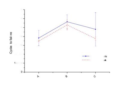
Two bonded and two welded wheels for the cases A, B and C were tested in these conditions. The obtained results are resumed in figure 19.
Notwithstanding the limited number of fatigue tests conducted, the obtained results showed a peculiar situation. It seemed that both the systems reached an apex of their fatigue resistance in the case of the samples B (low interference level). The wheels characterized with higher interference levels (case A) and transition fits (case C) failed at lower number of cycles. Moreover, meanwhile the bonded wheels provided repeatable data, a high variability was recorded for the welded wheels, probably imputable to the quality of the welding.
 700000 600000 500000
^ 400000 ■r, 300000
200000 —
Welded whee
Bonded whees
00000
Interference level
Figure 19. Results of the rolling tests of A, B and C wheels with the radial and lateral loads augmented of 15%.
It was reasonable to state that the shear resistance of the bonded wheel and its fatigue behavior were not correlated. In fact, the case C showed the best performances in static shear but a worse fatigue behavior. While the size of the bonded area seemed to govern the decoupling resistance, the interference seemed to play the biggest role in ruling the fatigue behavior. Indeed, the interference level can be related to parameters such as the vibration frequency and the stiffness, which are important in the field of fatigue analysis.
The resultant strength of the examined hybrid interference fitted-ahdesive bonded joints was not always a result of the sum between the adhesive resistance and the interference contribution. The experiments carried out at laboratory level showed that different adhesive types provided dissimilar behaviors in the hybrid joint. Indeed, a greater influence of the adhesive on the maximum strength attainable for the hybrid joint was observed. Rheology of adhesive played a relevant role in determining how much adhesive was spewed away from the joint. If a few quantity of adhesive remained inside the
joint the adhesive contribution resulted lowered, also affecting the total resistance of the hybrid joint. In the case of the flexibilized and thoughened epoxy adhesive, the enhancement provided by the interference contribution seemed to influence in the same way the total resistance of the hybrid joints.
The exploitation of adhesives with different flexibility did not provide changes in the stiffness of the hybrid systems, which seemed rather dependent on the interference. Moreover, the presence of the interference positively affected the fatigue behavior of the cylindrical joints. Hybrid joints sustained 106 fatigue cycles at load amplitudes equal to an higher percentage of their static resistance compared to the clearance joints.
In the application of the hybrid joint in the wheel system, it was observed that the joint geometry played a relevant role on its performances. The presence of the disc flange angle and the deformability of the rim well created zones of clearance inside the joint. The more the interference the less the quantity of adhesive penetrated inside the clearance. The extent of the bonded area strongly affected the total static resistance of the hybrid joint. On the contrary, the fatigue life of the bonded wheel seemed to be independent to its resistance to the decoupling, and to depend on the interference level to a large extent.
 9 октября, 2015
  Pokraskin
 Опубликовано в рубрике