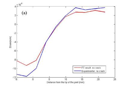
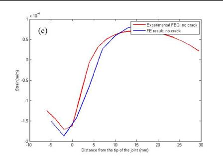
A servo-hydraulic system from MTS Landmark™ Testing Solutions with a capacity of 100 kN was used, in an environment with controlled temperature and humidity. A static load was applied to the specimens with strain gauges and specimen with FBG array without any crack.
|
|
|
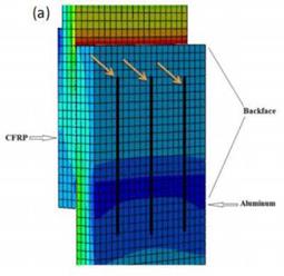
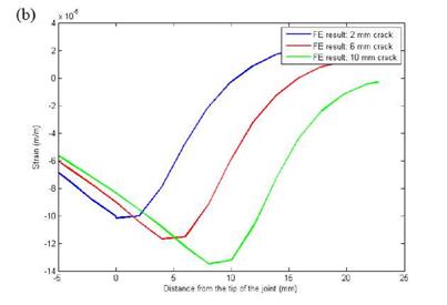
Figure 9. (a) FE model with three lines to be analyzed for BFS distribution, (b) BFS distribution from FE analyses for different crack lengths. |
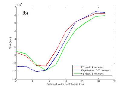
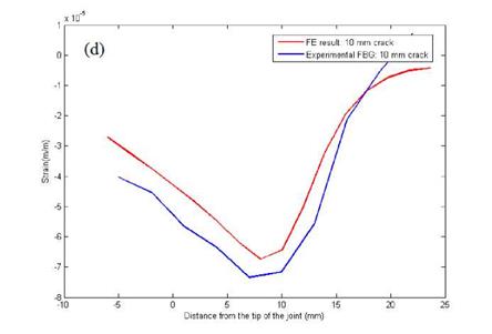
Similarly, a static load was applied to the specimen with strain gauges with a crack of 5.7 mm and to the specimen with FBG array having a precrack of 10 mm.
The conditioning of FBG sensors was done using an HBM DI410 interrogator (4-channel device, 1000 measurements/sec). Static investigations were first done in order to check the crack detection technique based on minimum negative peak of the BFS distribution. Then a fatigue test with a load ratio equal to 0.1 was carried out with one of the pre-cracked specimens.
|
|
|
Figure 10. (Continued). |
|
|
|
Figure 10. Static results of BFS distribution — by arrays of strain gauges for (a) no crack specimen, (b) specimen with 5.68 mm pre-crack; by an array of FBG sensors for (c) no crack specimen, (d) specimen with 10 mm pre-crack. |
The artificial crack was allowed to propagate for 150,000 cycles. During the test, a Matlab function, based on the correlation between crack tip position and the minimum of the BFS distribution obtained by FE analyses, evaluated the position of the crack tip. The propagation of the crack was also monitored by means of an optical microscope.
 31 декабря, 2015
  Pokraskin
 Опубликовано в рубрике