Acoustic emission consists of a rapid release of energy as a material undergoes fracture or deformation. In SHM, two important features of acoustic emission are important: its ability to perform remote detection of crack formation or movement at the time it occurs and to do this continuously [12].
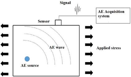
A schematic representation of acoustic emission (AE) technique is shown in Figure 3. When a crack initiates in a component under applied load, the crack acts as a source of AE waves which propagates in all direction. Sensor attached on the surface of the component records the AE waves and sends signals to the acquisition system for diagnosis.
It is important to note that, AE waves generated at the damage location will have to propagate over a certain distance before detection takes place at the sensor’s location, and therefore, the shape of an AE wave can be altered due to attenuation, reflection, mode conversion, and dispersion. It is highly recommended to have a good understanding of these effects as they can have a significant effect on the AE signals obtained during a test.
|
Figure 3. Schematic reprentation of Acoustic emission (AE) technique. |
As the mechanical properties of a composite structure are strongly dependent on the direction along which they are measured, this in turn will result in wave propagation effects that vary from one direction to another. For example, in a unidirectional laminate, waves will generally propagate faster along the fiber direction than along the direction perpendicular to the fibers. These effects have to be taken into consideration.
Ducept et al., [13] studied mixed mode failure criteria for a glass/epoxy composite and an adhesively bonded composite joint. In their study, the initiation failure point detected by acoustic signal and by the non-linearity point on the load/displacement curve and found good correspondence. Magalhaes et al., [14] studied the application of acoustic emission to investigate the creep behavior of composite bonded lap shear joints.
 7 декабря, 2015
  Pokraskin
 Опубликовано в рубрике