The dominant class of pearl luster pigments is based on platelets of natural mica coated with thin films of transparent metal oxides [5.122-5.125, 5.127-5.130, 5.137]. The mica substrate acts as a template for the synthesis and as a mechanical support for the deposited thin optical layers of the pearl luster pigments. Mica minerals are sheet layer silicates. Pearl luster pigments are usually based on transparent muscovite mica; only some are based on synthetic phlogopite. Although muscovite occurs worldwide, few deposits are suitable for pigments. Natural mica is biologically inert and approved for use as a filler and colorant.
Selection and pre-processing of the mica substrate is one of the key factors which determine the quality and appearance of nacreous pigments. The mica manufacturing process starts from rough mica blocks. These are ground and then classified into different particle size distributions affecting the quality of the pigments. The aspect ratio of the final pigments depends on the particle size distribution of the mica platelets, which have a thickness of 300-600 nm and various diameter ranges (e. g., 5-25, 10-50, 30-110 pm). Since light is regularly reflected from the planes of the metal-oxide-coated mica and scattered from the edges, brilliance and hiding power are inversely related to each other.
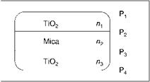
A mica pigment coated with a metal oxide (Figure 5.17) has three layers with different refractive indices and four phase boundaries Pi-P4: Pi / TiO2 /P2 / mica / P3 / TiO2 / P4. Interference of light is generated by reflections of all six combinations of phase boundaries, some of which are equal: P1P2 = P3P4, P1P3 = P2P4, P;iP4, andP2P3. The thickness of the mica platelets varies in accordance with a statistical distribution. Consequently, interference effects involving the phase boundaries between the mica substrate and the oxide coating add together to give a white background reflectance. The interference color of a large number of particles therefore depends only on the thickness of the upper and lower metal-oxide-coating layers.
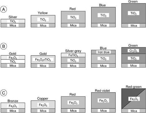
The development of the mica-based pigments started with pearl luster colors (Figure 5.18(A), TiO2-mica). This was followed by brilliant, mass-tone-colored, combination pigments (i. e., mica-TiO2, and another metal oxide) with one color (interference
|
Fig. 5.17 Structure of a titanium dioxide mica pigment with the four existing interfaces. |
color same as the mass tone) or two colors (interference and mass tone different) that depend on composition and viewing angle (Figure 5.18(B)). In the 1980s further development was made by coating mica particles with transparent layers of iron(III) oxide (Figure 5.18(C)).
|
Fig. 5.18 Schematic illustration of different metal oxide mica pigments. A) interference colors; B) combination pigments; C) metallic colors. Only the upper half of the pigments is shown. |
Titanium Dioxide-Mica
The first multilayer pigments were marketed in the 1960s as TiO2-coated muscovite micas. Two different processes are used for coating mica in aqueous suspension on a commercial basis:
1. Homogeneous hydrolysis
100 °C
TiOSO4 + Mica + H2O———————- > TiO2-Mica + H2SO4
2. Titration
TiOCl2 + 2 NaOH + Mica—————— > TiO2-Mica + 2 NaCl + H2O
The pigments are then dried and calcined at 700-900 °C. The titration (chloride) process is preferred for interference pigments with thick TiO2 layers because it is easier to control. Chemical vapor deposition in a fluidized bed has also been proposed: >100°C
TiCl4 + 2 H2O + Mica———————— > TiO2-Mica + 4 HCl
When TiO2 is precipitated onto muscovite under reaction conditions unfavorable for side precipitation, e. g., pH >1.5, only the anatase modification is formed. Even after annealing at 1000 °C, no rutilization is found in the layer, whereas the free titania is transformed completely into rutile at about 700 °C.
Rutile has a higher refractive index than anatase. This yields a stronger reflectivity and pearlescence effect. Therefore, processes have been developed to create a rutile layer on mica. A thin layer of SnO2 is precipitated as a continuous layer onto the substrate, and then the TiO2 layer is created using the usual process. SnCl2, or better SnCl4, can be used as precursors for the SnO2 precoating. SnO2 acts as a template because its lattice parameters are close to those of rutile.
The desired interference color determines the thickness of the titania layer. For a silver white pigment 50 nm of anatase is needed and for a blue interference color about 120 nm. The sequence of interference colors obtained with increasing TiO2 layer thickness agrees with theoretical calculation in the color space (Figure 5.19). A cross section of a TiO2-mica pigment is shown in Figure 5.20.
Special effect pigments suitable for outdoor applications must meet the highest standards for color fastness and weather resistance. These pigments are coated additionally with thin layers of transparent and colorless oxidic compounds. These layers increase the light resistance by reducing the photoactivity of the titanium dioxide surface. In addition, the interaction between pigment and binder is optimized.
TiO2-mica pigments are used in all color formulations of conventional pigments where brilliance and luster are required in addition to color, i. e., in plastics, coatings, printing, and cosmetics. Table 5.15 contains a comparative overview of TiO2-mica, basic lead carbonate, bismuth oxychloride, and natural fish silver pigments. Some further physical data are summarized in Table 5.16.
Iron Oxide-Mica
Like titanium dioxide, iron(III) oxide is suitable for coating mica platelets. It combines a high refractive index (metallic luster) with good hiding power and excellent

weather resistance. Commercial Fe2O3-mica pigments are produced by precipitation of iron(II) or iron(III) ions in aqueous mica suspensions and calcination of the resulting coated particles at 700-900 °C:
2 FeCl3 + Mica + 3 H2O ^Fe2O3-Mica + 6 HCl
|
Tab. 5.15: Properties and applications of pearl luster pigments.
|
|
Tab. 5.16: Technical data of pearl luster pigments.
|
It is also possible to produce iron oxide-mica pigments by a direct CVD fluidized bed process in which iron pentacarbonyl is oxidized and Fe2O3 is deposited on the mica surface.
Independent of the synthesis route, iron(III) oxide crystallizes in the a-modification (hematite) after calcination. Brilliant, intense colors are obtained with 50-150 nm layers of Fe2O3 (hematite) on muscovite (see Figure 5.18 (c)). Absorption and interference colors are produced simultaneously and vary with layer thickness. The red shades are especially intense because interference and absorption enhance each
other. An intense green-red flop with different viewing angles is possible at a Fe2O3 layer thickness, producing green interference.
 5 января, 2016
  Pokraskin

 Опубликовано в рубрике