In the case of center luminescence, the emission is generated on an optical center, in contrast to e. g. emission which results from optical transitions between host lattice band states. Such a center can be an ion or a molecular ion complex.
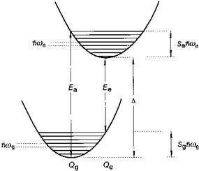
One speaks of characteristic luminescence when, in principle, the emission could also occur on the ion in vacuum, i. e. when the optical transition involves electronic states of the ion only. Characteristic luminescence can consist of relatively sharp emission bands (spectral width typically a few nm), but also of broad bands, which can have widths exceeding 50 nm. Broad emission bands are observed when the character of the chemical bonding in the ground and excited states differs considerably. This goes hand in hand with a change in equilibrium distance between the emitting ion and its immediate chemical environment and is commonly explained with the configuration coordinate diagram (Figure 5.44). Broad bands are observed for many optical transitions in the partly filled d-shell of transition metal ions (d ^ d transitions), and also for transitions between the 5d shell and the 4f shell of rare-earth ions (d ^ f transitions) and for emission on s2 ions (these ions possess a ‘lone pair’ of s electrons), like Tl+, Pb2+ or Sb3+. Sharp emission bands are characteristic of optical transitions between electronic states with chemical bonding character (almost)
|
Fig. 5.44 Configurational coordinate diagram. |
the same for the ground and excited states, and for the same reason also for optical transitions between electronic states that hardly participate in the chemical bonding (e. g. f ^ f transitions on rare-earth ions).
In the case of optical processes involving electronic states which participate in the chemical bonding, the nature of the bonding (covalent, ionic) and the symmetry of the site at which the emitting ion is incorporated play a very important role. This is generally described by ligand field theory, which is not treated here. However, the term symbols for the description of the electronic transitions will be used.
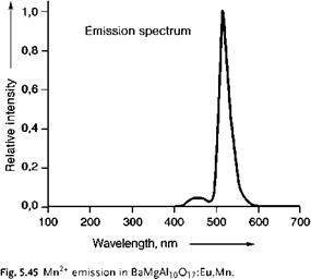
An example of a broad d ^ d emission band (in the green part of the spectrum) is the emission of Mn2+ in BaMgAl10O17:Eu, Mn (Figure 5.45). The weak blue emission band originates from ad ^ f optical transition on Eu2+.
|
|
The green emission is generated by a d ^ d optical transition on the Mn2+-ion with high spin d5 electronic configuration (all electrons have their spin oriented in the same direction). The optical transition leading to emission is 4T1g ^ 6A1g. The electronic configurations in the ground and excited state are (t2g)3 (eg)2 and (t2g)4 (eg)1, respectively. The emission generated reflects how the optical properties of the ion depend on its chemical environment. This luminescent material can be applied as green phosphor in very high quality fluorescent lamps and also in plasma display panels.
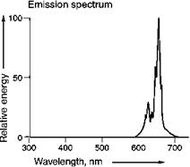
An example of d ^ d emission, consisting of a few relatively sharp bands is the emission of Mn4+ in Mg4GeO55F:Mn (Figure 5.46). Please note that the emitting ion is the same, only its charge (and therefore its electronic configuration) is different. In this case, the optical transition consists of a spin-flip transition within the (t2g)3 manifold (2E ^ 4A2 transition), i. e. hardly changing the character of the bonding. This manifests itself in relatively narrow emission bands. This phosphor can be used as red primary in fluorescent lamps. It enables the reproduction of deep red colors.
Fig. 5.46 Mn4+ emission in Mg4GeOs.5F.
 The optical transitions, discussed above, are spin forbidden and consequently rather slow (decay time of the order of ms).
 |
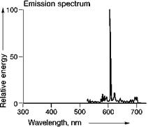
Most rare earth ions show sharp emission bands, due to optical transitions within the f-manifold, e. g. Tb3+ ^^-configuration) and Eu3+ ^^-configuration), in which the emission spectra of (Ce, Tb)MgAl11O19 and Y2O3:Eu are reproduced (Figures 5.47 and 5.48). Both these phosphors are applied in high quality fluorescent lamps and Y2O3:Eu is also used in projection television, based on cathode-ray tubes. In such projection televisions, small cathode-ray tubes are used, the images of which are projected onto a large screen.
There are a few green Tb3+-based phosphors, suitable for application in fluorescent lamps. Despite intensive research, no substitute for Y2O3:Eu with the same spectral properties has been found, leaving it the only red primary with line emission at about 611 nm. The width and position of the emission bands originating from optical transitions within the f-electronic shell are almost independent of the chemical environment. The relative intensity of the separate bands, however, depends on the crystal lattice. The transitions on many rare-earth ions are spin — and parity — forbidden and therefore rather slow (in the ms range). However, for a number of rare-earth ions, broad emission bands are also known, due to d ^ f emission, e. g.
Fig. 5.48 Emission spectrum ofY2O3:Eu.
 Eu2+ (4f7-configuration) or Ce3+ (4f1-configuration). These transitions are allowed and consequently very fast (in the gs range or even faster). Quite a few very important commercial phosphors are based on rare-earth ions. Rare-earth based phosphors are very frequently applied in very demanding applications.
5.5.3.2
 19 января, 2016
  Pokraskin

 Опубликовано в рубрике