Structural design. The comments which follow are applicable to the case of open sandwich slab elements of either constant depth or inverted catenary section acting compositely with steel plate girders, in accordance with BS 5400 (4). For constant depth elements an initial design approach may be to assume that the deck behaves as a series of laterally connected T-beams. The grillage method may then be used for an analysis of the global load distribution, although a number of caveats should be observed(5, 6). Analysis of the inverted catenary slabs is probably best accomplished using the finite prism technique(7), together with some local section design based upon conventional reinforced concrete theory. For initial sizing of the precast units, reference may be made to Table 8.1 which provides trial concrete and steel thicknesses for a range of longitudinal beam spacings.
Conventional bar reinforcement is advised for incorporation in the top surface of open sandwich decks to control cracking and to provide continuity. Tensile stresses will occur in the transverse
|
Table 8.1. Initial sizing of open sandwich panels
|
direction over the main beams in all decks and longitudinally over intermediate supports of continuous decks. Some suggested details illustrating the reinforcement suggested to accommodate these local stresses are incorporated in Figs. 8.3-8.6.
Punching shear failure is to be guarded against in both types of deck, and particularly over the relatively thin crown of inverted catenary sections. It seems as though the guidelines in CPI 10 (8) will provide adequate resistance in this respect, based upon laboratory studies(9). Fatigue behaviour of such slabs has been demonstrated to be very good, both in laboratory investigations and under road-traffic conditions.
Manufacture. Slabs consist of a thin steel plate with adhesive against which concrete is cast. Plate thicknesses should always be at least 3 mm, and the plate’s surface(s) should be cleaned, degreased and gritblasted prior to bonding. Adhesive requirements are broadly similar to those specified for repair and strengthening purposes (see Chapter 6), although particular regard should be paid towards the amount of free moisture associated with fresh concrete and the highly alkaline nature of hardened concrete as an adherend.
A flexibilised cold-curing epoxide adhesive containing an aromatic amine hardener is likely to be the most successful, particularly if used in two layers or in conjunction with a priming layer. Alternatively an adhesive containing a modified aliphatic polyamine hardener may be suitable, in conjunction with a primer recommended by the manufacturer. The adhesive layer should be about 1 mm thick, and the concrete cast against it whilst this is still tacky. A rapid curing adhesive is not necessary; one which cures to the required mechanical properties in about 7 days will suffice. However, in view of the likely sustained loading to be borne by the adhesive, its flexural modulus and Tg should not be too low in order to avoid creep effects. The underside of the plate should be painted, or at least primed, as part of the final overall corrosion protection system.
Conventional or lightweight aggregate may be used to construct the slabs. The fresh concrete should be applied to the adhesive coated plate within 40 minutes of mixing the adhesive, requiring a carefully monitored working sequence. Compaction should be effected using either internal or external vibrators, and curing should be conducted in the normal manner. Curing at elevated temperatures, particularly using steam, is not recommended.
Installation. The installation of slabs into a bridge deck requires the careful consideration of a number of details. Firstly, lifting eyes must be incorporated into the tops of such slabs which are connected to the soffit steel. Secondly, the method of ensuring composite action and continuity must be decided upon. Composite action with the longitudinal beams may be assured by the use of shear studs, welded to the top flanges of the beams, which project through predrilled holes along the projecting soffit steel of the slabs. The slabs may also be ‘bedded’ on a layer of adhesive applied along the flange tops of the longitudinal beams. This provides shear resistance as well as maintaining a good seal between the slab and the beam. In situ concreting between the slabs can then be carried out after continuity reinforcement has been placed.
The continuity details outlined here assume that the open sandwich deck has been designed for full transverse continuity over the longitudinal plate girders, although a simpler detail may result if the slabs were assumed to be simply supported between the plate girders. The suggestions here are based partly upon experience gained during laboratory trials, but mainly on those employed in the construction of a 6 m span bridge constructed for Tayside Regional Council’s Roads Department to the south of Loch Tummel (Fig. 8.2)(10). The structure has been in service since 1985.
|
Fig. 8.2. Installation of open sandwich deck slabs on bridge south of Loch Tummel, Tayside. |
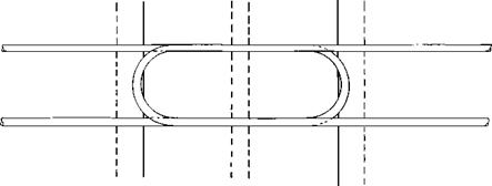
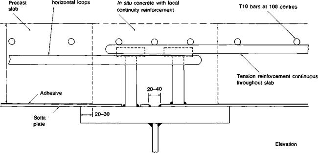
Transverse continuity may be provided by using an in situ concrete connection containing looped reinforcement cast into the slabs (Fig. 8.3); an alternative arrangement using folded steel plates may also be used (Fig. 8.4). The primary shear connection is provided by shear studs welded alternately to the soffit plate and the longitudinal beam flange. It is important that the precast/ш situ construction joint occurs well away from the beam flange to avoid excessive rotations and subsequent slab distress under traffic loads.
Longitudinal continuity between slabs in regions of sagging moments may be made by using a bonded or welded cover plate (Fig. 8.5). Top bar reinforcement is optional in this case, to control differential shrinkage between the precast and in situ concrete. In regions of longitudinal hogging moment, the top of the slabs will need to be reinforced to control flexural tension cracking. Conventional bar reinforcement may be cast into the slabs as shown by a typical joint detail in Fig. 8.6. Naturally it is important to provide a suitable corrosion protection method for the underside of the slab soffit steel. Normally, painting of the bridge soffit would be carried out during construction, and then within a normal maintenance schedule.
|
|
|
300 to 400 |
|
Precast slab grade 40 concrete |
|
|
|
|
|


|
|
|

|
|
Comparative example. A comparative costing exercise was conducted on the re-design of a typical continuous highway bridge with an open sandwich roadway deck (Fig. 8.7). The Tummel Bridge on the Pitlochry by-pass (A9), Tayside, consists of four steel plate girders which act compositely with a 225 mm thick reinforced concrete deck continuously supported over spans of 40 m, 70 m, and 40 m respectively. The study suggested that deck slabs consisting of a 150 mm thick concrete core and a 3 mm thick steel soffit plate would provide a suitable alternative deck slab. A re-costing established a saving of some 12% in superstructure cost if this form of deck was incorporated in designs carried out to latest Department of Transport specifications.
 12 сентября, 2015
  Malyar


 Опубликовано в рубрике