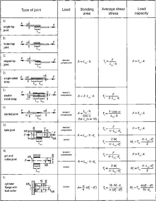
Many factors influence the load capacity of adhesive bonded joints [3-7]. In a first approach, simplified design rules may be used to estimate the average stress in basic joint layouts [3] (Figure 6.10).
|
Figure 6.8 Avoiding peeling in bonded joints [1]. |
|
Favorable Not favorable |
|||
|
u |
________ і |
—- , |
|
|
* |
J О |
||
|
г * |
a |
||
|
Figure 6.9 Avoiding tensile stress in bonded joints [1]. |
When creating adhesively bonded joints with different adherent materials, thermal internal stresses will occur that superimpose on the external mechanical loads and thus reduce the load capacity of the joint. Elastic adhesives are superior in this type of application as they reduce the level of thermal stress, especially when applied in thick bond-lines (Figure 6.11).
In a single lap shear joint, in addition to shear stress, bending moments occur due to the eccentricity of the load introduced. This bending moment causes additional normal stresses within the bond-line (Figure 6.12).
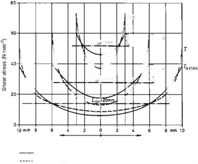
Matting [8] calculated the distribution of the shear stresses along the center axis in single lap shear joints, with and without taking into account the bending moments. The stress distribution, for three different overlap lengths, is illustrated graphically in Figure6.13.Notethatthedistributionbecomesincreasinglyuniform — thatis, thestress concentration factor C = Ta, max/Tam decreases with decreasing overlap length, Lov.
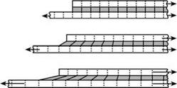
When using brittle adhesives the calculations and representations of the shear stress distribution in single overlapped shear joints can be based on the simplified assumption that the adhesives had a quasi-elastic deformation behavior. Present-day adhesives, however, are usually plasticized and can therefore reduce stress concentration by plastic deformation (Figure 6.14).
|
Figure 6.10 Simplified calculation of average stresses in bonded joints. |
|
|
|

|
a max |
Distance from the center of the overlap
without bending moment with bending moment
Figure 6.13 Stress distribution, according to Matting [8], in a single lap shear joint with different overlap lengths.
 |
|
 Overlap length
Figure 6.15 Calculated (A, B) and measured (C) stress distribution in a single lap shear joint (half overlap length).
Figure 6.15 compares the theoretical stress distribution calculated with elastic deformation properties of the adhesive (according to Goland-Reissner) to a stress distribution calculated with real (elastic-plastic) deformation of the adhesive, and to experimental data [9].
The experimental data show a more uniform stress characteristic than expected due to viscoelastic deformation occurring under the effect of repeated load, an increase in temperature, and by a slight softening under the influence of moisture.
 3 октября, 2015
  Pokraskin


 Опубликовано в рубрике