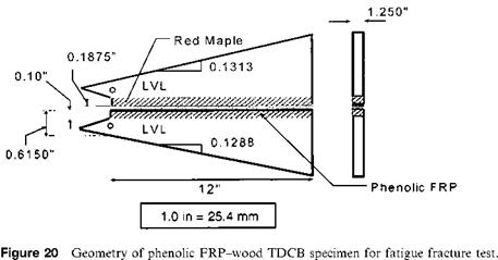
A TDCB specimen designed by the Rayleigh-Ritz method [8] was used for fatigue tests on FRP-wood interfaces. The TDCB specimen was contoured to achieve a constant rate of compliance change with respect to crack length, dC/da. The details of the specimen design and applications for FRP-wood interface fracture studies [8] are given in previous sections. The geometric details of the TDCB specimen are shown in Fig. 20, and the adher — ends consisted of red maple and phenolic FRP with the contoured portions made of LVL. The adhesive used for bonding phenolic FRP to wood was RF.
Cyclic tension-tension fatigue tests were conducted on a computer controlled MTS servo hydraulic machine. The load ratio R (the ratio of minimum load to the maximum
 |
load) was kept constant during the testing of each group of samples. Three groups of tests for load ratios R of 0.1, 0.3, and 0.5 were carried out under load control mode. A constant frequency of 1 Hz and a sinusoidal waveform were used for all the tests. Since only the relative value of the crack opening displacement (COD) is needed, a crosshead displacement instead of an extensometer displacement was used to measure the COD. The test environment was room temperature (23 ± 2°C) and open laboratory conditions for all the samples.
The TDCB specimen (Fig. 20) was used for evaluating fracture toughness of bonded FRP-wood interfaces under mode-I loading [5], and the strain energy release rate G is given in Eq. (1). For one complete cycle, the maximum and minimum strain energy release rates are
![]() P • dC
P • dC
G min
Gmin —
2b da
The strain energy release rate range, AG — Gmax — Gmin, is easily obtained from the difference of Eqs. (3) and (4). For the TDCB specimen, the constant compliance rate change (dC/da) with respect to crack length a is obtained, and therefore, the constant strain energy release rate range AG is acquired for constant cyclic loading.
The accuracy of the crack propagation rate da/dN depends on the measurement of the crack length, which is a formidable problem confronted by researchers in fracture mechanics. The COD is much easier to measure than the crack length for the TDCB specimen. The difficulty of measuring the crack propagation rate is avoided by using the COD propagation rate. The transformation from COD propagation rate dCOD/dN to crack propagation rate da/dN is given as
da da dC 1 dCOD
dN — dCdN — kP dN () where N is the number of cycles, P is the applied load, and k is a constant equal to the reciprocal of dC/da. A typical COD propagation rate diagram from fatigue test is illustrated in Fig. 21.
 16 июля, 2015
  Malyar
  Опубликовано в рубрике