Bryan H. River
Forest Products Laboratory, USDA-Forest Service, Madison, Wisconsin, U. S.A.
Adhesives are arguably the most important fastening system used with forest products. Large volumes of adhesives are used successfully in wood-, particle-, and fiber-based industries. In fact, large and important industries such as panel products would not exist without adhesives. However, the sometimes unpredictable and misunderstood behavior of wood-adhesive joints, particularly fracture, is a major constraint to improving the performance of existing products and the development of new wood-adhesive marriages. In this chapter I briefly examine current understanding of fracture mechanisms in wood — adhesive joints. The discussion is limited to joints bonded with those adhesives having sufficient strength and rigidity to cause fracture in the wood adherends. Primarily, these are the rigid, thermosetting adhesives such as phenol and urea-formaldehyde, nonrigid epoxy and thermosetting poly(vinyl acetate) adhesives, and some thermoplastic types such as poly(vinyl acetate).
The fracture of strong wood-adhesive joints (e. g., in the catastrophic rupture of a large laminated beam) may be viewed (and heard) as a macrocracking process. It may also be viewed microscopically and heard by acoustic emission technology in flakeboard as a microcracking process resulting from shrinkage. These examples are not meant to imply that beams do not fail by microprocesses or that particleboard does not fail by macro processes. Both of these examples of fracture begin with the microscopic initiation of a crack at some flaw in the material or, in this case, the bonded joint.
The initial flaw can be a discontinuity, such as a void, or an abrupt change in material properties. By nature, wood contains innumerable discontinuities, such as the cell cavity and transition zones between cell wall layers. An adhesive may contain air bubbles or fillers with properties different from the resin. A rough wood surface may not be completely wetted by the adhesive, leaving voids at the interface. The adhesive and wood also have different mechanical properties. When a joint or bonded material is subjected to some force, the resultant stress is heightened or concentrated around the discontinuities far above the average stress in the joint or material. Fracture results
The Forest Products Laboratory is maintained in cooperation with the University of Wisconsin. This article was written and prepared by U. S. government employees on official time, and it is therefore in the public domain and not subject to copyright.
when the stress at a discontinuity reaches the ultimate stress or strength of either the adhesive, the adherend, or the interface.
The stress conditions around a cracklike discontinuity can be described by the stress intensity factor (K), which is a function of the applied load, the size of the cracklike flaw, and the material. Fracture occurs when the stress intensity factor reaches a critical level, called the critical stress intensity factor or fracture toughness (Kc). Fracture mechanics relates the applied stress at which a material fractures to the critical stress intensity factor and the critical flaw size of the material:
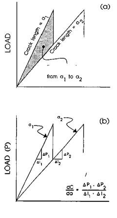
where sa is the applied stress at fracture, Kc the critical stress intensity factor, and a the crack length or flaw size. The stress intensity factor has been found useful for describing the fracture behavior of many materials. However, the stress intensity surrounding discontinuities in adhesive joints is extremely difficult to define because of the dissimilar materials combined in the joint. Therefore, the sensitivity of adhesive joints to stress and discontinuities is usually measured and described in terms of the energy required to initiate a crack or the energy released in forming a new crack surface (Gc) (Fig. 1). The critical stress intensity factor Kc and Gc are related through the elastic properties of the material:
K2 T
Gc = — E. (1 — v2) where E is the tensile modulus of isotropic adherends and v is Poisson’s ratio of adherends.
The crack initiation energy can readily be determined from a mode I cleavage test using a double cantilever beam specimen [1,2]. This method has been applied to wood — adhesive joints by many researchers [3-17]. The test requires the beam compliance (C), load at crack initiation (Pc), crack length at initiation (a), specimen thickness (t), and change in beam compliance (dC/da = change in displacement of load points/change in crack length) (Fig. 1b):
![]() P2 dC 2t da
P2 dC 2t da
Anderson and others [18] have reviewed these and other fracture test methods for evaluating adhesive bonds.
The load or force that causes stress around a discontinuity may be applied externally to a material or structure. More often, in bonded joints the force arises from differential shrinkage and swelling of the bonded members or particles. In adhesive joints and most wood products, forces tending to cleave the joint (mode I loading) are of primary importance. Sliding shear (mode II) and torsional shearing (mode III) forces are less important. However, most wood joints experience a combination of mode I with either mode II or mode III shear.
Whereas the fracture of bonded joints is due to the presence of critical discontinuity in a field of stress, the stress intensity or crack initiation energy of bonded joints and materials at which fracture occurs is also a function of the properties of the wood and the adhesive, the environment at a given time, changes in the environment, and external forces on the joint or bonded material. These relationships are explored in the following sections.
 to extend crack
LOAD DISPLACEMENT
Compliance (C)
* ДІ ЛР
LOAD DISPLACEMENT (I)
Figure 1 (a) Energy expended in forming new crack surface (shaded area), determined as the difference in the area under the load-displacement curve before crack extension (a1) minus the area of the load-displacement curve after crack extension (a2); (b) calibration procedure for determining the change in beam compliance with change in crack length (dC/da).
 10 июля, 2015
  Malyar
  Опубликовано в рубрике