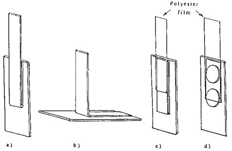
Although slight differences occur here and there, the universally recognized method to determine how well a pressure-sensitive system adheres is to apply the adhesive, which has been pre-coated onto a flexible carrier, to a rigid standardized test panel under very controlled conditions and environment, using a roller of standard weight, dimensions, and construction, in order to apply a controlled application pressure. Then the force required to separate the two is found out by peeling the flexible carrier at a controlled rate, at either 180° [9] or 90° [10] (Figs. 1a and b), the rate of both roll-down and peel usually being at 12 in. (300 mm) per minute, with various dwell times between roll-down and testing, from immediate to 20 min. The 90° test is usually chosen when the thickness of the backing prevents a 180° peel, but these two angles of peel tell a different story, the 90° peel being one of tensile stress, while the 180° peel is a combination of tensile and shear stress [11]. Also, it is to be noted that, while, both the 90° and 180° tests are being peeled at the same tester rate, the peel front of the 90° test is moving at twice the rate of the 180° test, and so the adhesion results of the two angles of peel are not truly comparable.
|
Figure 1 Peel adhesion testing: (a) 180° peel; (b) 90° peel; (c) reverse 180° peel; (d) adhesion of irregular shapes. |
|
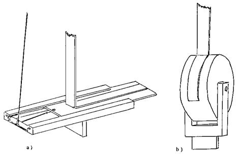
Figure 2 90 peel adhesion testing: (a) controlled 90 peel adhesion; (b) drum peel. |
To maintain a constant 90° angle during peel, a special jig is necessary that moves the test panel at the same rate as the tape is being stripped (Fig. 2a). An alternative method [9] is to apply the tape to a free-rolling drum, which automatically maintains 90° by rotating during the stripping process (Fig. 2b).
The work done in peeling is divided between that necessary to separate the adhesive from the test surface, and that required to bend the backing, and the latter value can be a significant component [12]. Further, the basic assumption is that the geometry of the peel process is constant. With more rigid backings this is not the case, the backing both creating a restrictive action to the intended angle of peel, and also requiring a considerable amount of energy to bend. The resulting adhesion with the same coat weight adhesive using various backings over a range of backing thickness can be seen in Fig. 3. There are two ways that the effect of the backing can be investigated and/or overcome. One is to use the same backing in a series of thicknesses, each coated with the adhesive under evaluation at a constant desired coat weight. By plotting the adhesion values obtained, then extrapolating, an adhesion value can be obtained that eliminates the effect of the backing. An alternative method is to attach the adhesive-coated strip, adhesive side exposed, to a test panel, using a high adhesion double-sided tape, then applying to this a strip of 25 pm polyester film very slightly wider than the test tape, following the same standard preparation and test procedures as if the polyester strip were the tape under test, and the exposed adhesive surface were the test panel (Fig. 1c). This would then enable tapes of backings of various stiffnesses to be compared without the backings interfering with the test geometry. This method is also applicable to irregularly shaped pressure-sensitive coated pieces, the recorded adhesion values obtained being correlated with the changes in dimensions of the piece, and brought to that of a standard width by calculation (Fig. 1d).
Adhesion testing of double-sided tapes is achieved by applying a 25 pm polyester film of suitable width to one side of the tape, then carrying out a standard adhesion test on the
 |
|
 Backing Thickness (mils)
Figure 3 Effect of backing on nominal 180o peel adhesion.
other side, recognizing that the polyester film will add to the value obtained as work done in peeling.
Tack is an indication of how quickly an adhesive can wet out, and so come into intimate contact with, a particular surface, and eventually reach its optimum adhesion. In effect what is attempting to be measured is a rate of change of adhesion with time. This rate of change is exponential in character, can be manipulated by the degree of applied pressure, and much of the event can occur in fractions of a second. The methods of measuring tack are many [13], with considerably different techniques and geometries, often being unique adhesion test methods, but they can be divided into three broad categories: those using a rolling ball, those using a modification of the peel test, and those using some form of probe.
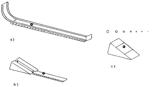
There are three major methods of tack test using a rolling ball method, each with its own variations, to suit a specific need, all involving rolling a small ball down a ramp and over the adhesive surface. The Douglas method (Fig. 4a), useful for adhesives with a high tack value, uses a 12 in. (300 mm)-radius ramp and a 1 |-in.-diameter steel ball, but different sizes and types of ball are also used, depending upon individual preference, one method using a table tennis ball, to create the minimum of pressure. The tack value is proportional to the reciprocal of the distance rolled, which also implies that the further
|
Figure 4 Rolling ball tack testing: (a) douglas; (b) PSTC; (c) dow. |
the ball rolls, the less reliable the method becomes, useful to 15 in. or so of ball travel. It has its problems, such as the contact area of the adhesive on the ball differing with the softness of the adhesive, the tendency of the tape to climb up the receding side of the ball, and the fact that after one revolution of the ball, the surface is now contaminated by adhesive. However, it is a useful comparative test for similar adhesive systems. The PSTC Test Method, No. 6 for Rolling Ball Tack (Fig. 4b) uses a 6in. (150mm) ramp at 21.5° with a slight curve at the exit, and a 7/16-in.-diameter steel ball. It is useful for adhesives with a lower tack value, with the same relationship and problems as the Douglas method useful for only the first few inches of travel. The Dow method (Fig. 4c) uses a 30° ramp, the adhesive-coated material being secured to the ramp face up with 3 in. of adhesive exposed. Then a series of steel balls each differing in diameter from the next by 1/32 in., are rolled individually in decreasing order, over the 3in. (75 mm) section of adhesive on the ramp, until one ball is stopped in the 3in. (75 mm) section. The tack value is taken as the numerator of the diameter of that ball. In all cases, the need for controlled conditions, and thorough cleaning and drying of the balls used, is essential.
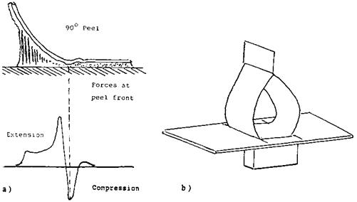
The commonest modified peel test, known as the ‘‘Quick-stick’’ or Chang test [14], uses the same equipment as for 90° peel (Fig. 2a), but the tape is laid on the test panel without any applied external pressure, then peeled immediately at 90°. The flaws in this method are that the adhesive continues to wet out the test panel with time, as it remains in contact, the precise time from application to testing being variable, but of much greater significance is that a zone of pressure follows the peeling action, governed somewhat by the flexibility of the backing, so that the tape effectively applies itself to the panel with pressure immediately following the peel zone [15] (Fig. 5a). In effect, it becomes a 90° adhesion test. One other well-known method, known as the loop tack method [16] (Fig. 5b), makes a loop of a 1-in.-wide sample of the tape, adhesive exposed, then this exposed adhesive is touched to a horizontal test panel with minimal pressure, to bring a definite area into contact. The force required to remove the loop, which is tested as for a
|
Figure 5 Quick-stick tack testing: (a) compressive effect of 90 peel; (b) loop tack testing. |
90° peel, is recorded as the tack value. This is essentially two Quick-stick tests, back to back, and therefore has the same flaws.
There have been various methods of probe tack testing, which have included using a ball bearing with supporting ring [17], or a large hemispherical probe [18], but one method now dominates, which is the Hammond or Polyken probe tack tester [14] (Fig. 6a). This method has the latitude of a variable pressure, a variable dwell time, a variable rate of removal of the probe, probes of various construction, and even the option of a heated probe. Bringing the probe and adhesive surface together to ensure uniform contact can be difficult, even when using a probe of small diameter, the standard being a flat surface stainless steel probe of 0.5-cm2 area, as there is a tendency to trap a very small air bubble. A slightly domed probe can overcome this [19]. Too low an application pressure will give nonuniform contact; too great a pressure causes the value obtained to plateau out, as will too great a dwell time before separation of the probe. The standard test conditions are 100-g/cm2 loading, with a 1-s dwell time and 1-cm/s removal, but this can be adjusted to suit certain adhesive systems. The separation mechanism is in actuality a very low angle circular peel (Fig. 6b) at very high speed, as has been shown by high speed photography [20]. While the probe tack method has not yet been fully adopted, when understood, it gives the most meaningful data.
Variations in test results for tack from test to test for a given sample are common, possibly because such a small area of the adhesive surface is under examination at each test, and for this reason, whatever test method is used for tack testing, a number of checks are necessary to obtain a statistically meaningful result.
 7 июля, 2015
  Malyar
 Опубликовано в рубрике