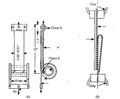
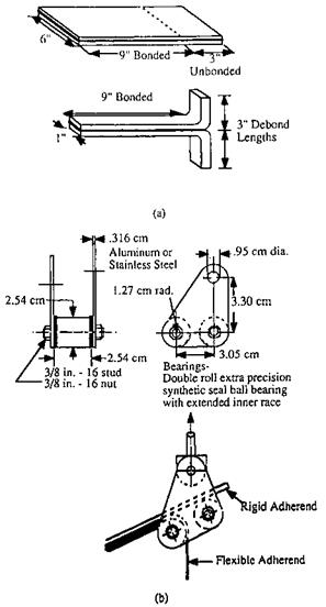
Another common type of test is the peel test. Figure 8 shows four common types of peel specimens. One can understand the test described in ASTM D-1876 by examining Fig. 8a.
|
Figure 8 Some standard peel test geometries: (a) T-peel test specimen, ASTM D-1876; (b) typical testing jig used in ASTM D-1876; (c) climbing drum peel test, ASTM D-1781; (d) 180° peel test, ASTM 903. |

|
||

![]()
In this adhesive peel resistance test, often called the T-peel test, two thin 2024-T3 aluminum or other sheets typically 152 mm wide by 305 mm long are bonded over an area 152 mm wide by 229 mm long. The samples are then usually sheared or sawed into strips 25 mm wide by 305 mm long (at times, the sample is tested as a single piece). The 76-mm-long unbonded regions are bent at right angles, as shown in Fig. 8a to act as tabs for pulling with standard tensile testing grips in a tensile testing machine.
In a related test, one of the adhering sheets is either much stiffer than the other or is firmly attached to a rigid support. Various jigs have been constructed to hold the stiffer segment at a fixed angle to the horizontal and, by using rollers or other means, allow it to ‘‘float’’ so as to maintain the peel point at a relatively fixed location between the grips and at a specific peel angle, as show schematically in Fig. 8b (see, e. g., ASTM D-3167).
ASTM D-1781 describes the climbing drum peel test that incorporates light, hollow drums in spool form. The sample to be peeled is attached on one end to the central (smaller) part of spool. The other end of the sample is affixed to the clamp attached to the top of the crosshead of the tensile testing machine, as illustrated in Fig. 8c. Flexible straps are wrapped around the larger-diameter part of the spool and attached to the other crosshead of a loading machine. Upon loading, the flexible straps unwind from the drum as the peel specimen is wound around it and the drum travels up (hence the name ‘‘climbing drum peel test’’), thereby peeling the adhesive from its substrate.
One of the simplest peel tests to conduct is the 180° peel test described in ASTM 903, Standard Test Method for Peel or Stripping Strength of Adhesive Bonds. In this test, one adherend is much more flexible than the other, so that upon gripping and pulling the two unbonded ends, the sample assumes the configuration shown in Fig. 8d.
Clearly, peel strength is not an inherent fundamental property of an adhesive. The value of the force required to initiate or sustain peel is not only a function of the adhesive type but also depends on the particular test method, rate of loading, nature, thickness of the adherend(s), and other factors [17]. Regardless, the peel test has proven to be a useful test for a variety of purposes.
The authors have been impressed with the interesting studies at the University of Akron [18,19], where Gent and his associates have used a peel test to measure the ‘‘work of adhesion.’’ The work of adhesion is essentially synonymous with adhesive fracture energy, discussed in Section III. C. Gary Hamed has published an article reviewing some of the work at Akron [17]. This paper describes how peel tests have been used to, among other things, (1) verify the usefulness of WLF time-temperature superposition, (2) investigate dependence of the adhesive fracture energy on bond thickness, (3) study adherend thickness effects on adhesive strength, and (4) examine the effects of peel angle. J. R. Huntsberger has also written an interesting discussion on the interpretation of peel test results [20]. Others who have analyzed the stresses, energy dissipation, slip-stick phenomena, and other aspects of peel adhesion include Kaelble [21,22], Igarashi [23], Gardon [24], Dahlquist [25], Bikerman [26], and Wake [27].
Another type of test, somewhat related to both tensile and peel, are the cleavage tests, such as described in ASTM D-1062 and D-3807. This test uses a specimen that resembles the compact tension specimen used for fracture of metals except that there is an adhesive bond line down the sample center. The stresses for such a geometry are nonuniform, but typical test results are given as force per width (i. e., failure-loaded divided by bond width). ASTM D-3807 uses a specimen fabricated by bonding two narrow, long rectangular beams together to form a split double cantilever beam. The force required to initiate separation between the beams is measured and reported as average load per unit width of beam. ASTM 3433, 3762, and 5041 also make use of cleavage specimens. These are discussed in Section III. C because they are commonly used for determination of adhesive fracture energy. D-1184, Standard Test Method for Flexure Strength of Adhesive Bonded Laminated Assemblies, makes use of standard beam theory to calculate the interlaminar shear strength in laminated beams loaded to failure.
 6 июля, 2015
  Malyar
 Опубликовано в рубрике