The surface preparation of steel adherends for joint testing should be as follows.
(1) If necessary, remove heavy layers of rust by hand, or by mechanical abrasion with emery cloth, or by wire brushing, to give rust grades A or В as defined by Swedish Standard SIS 055900 (6).
(2) Either wash with detergent solution, rinse thoroughly with cold
 |
|
Compliance spectrum 150
Fig. A4. ‘All-adhesive’ tensile test.
water and dry in a stream of warm air and with clean absorbent paper, or wipe with a suitable solvent and allow to evaporate.
(3) Gritblast to grade Sa2| of Swedish Standard SIS 055900 (6) to achieve a mean maximum peak-to-valley depth of at least 50 pm, using a hard angular clean metal grit which is free of any grease contamination. For stainless steels, a non-ferrous grit — e. g. alumina based — should be used.
Abrasive dust remaining on the adherend surfaces after blasting should, ideally, be removed by brushing, blowing or vacuuming; solvent degreasing at this stage is not recommended. If a compatible primer is to be employed, all joint tests should be carried out using both unprimed and primed steel surfaces. Joints should be manufactured in jigs to provide a light clamping force during the cure, using carefully positioned internal wire or external steel spacers to control the adhesive thickness at a constant value between 0.5 and 1.0 mm.
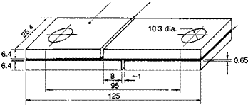
Joint fracture toughness. The initial mode I fracture toughness К |C, obtained from the mean of several tests using wedge cleavage specimens, an example of which is depicted in Fig. A.5, should not be less than 0.5 MN m-3/2. The tests should be carried out at 20 °С using a wedge insertion rate of approximately 50 mm/min. The crack extension (a) should be measured on both sides of the specimen, e. g. by using a travelling microscope. The equation for the fracture of energy of the specimen is(7):
I 3.2 f 0.65
![]()
 where Es is the elastic modulus, and h the thickness, of the steel adherends. The fracture toughness KiC can then be obtained by using the expression Ki = EaGiC for plane stress, where Ea is the elastic modulus of the adhesive obtained as described above. Such specimens may be further employed for stressed durability testing, by monitoring the rate and location of crack growth for different exposure environments^).
Lap shear strength. Tests should be carried out over a range of temperatures, specifically including -25 °С, +20 °С and +45 °С, using bright mild steel adherends. The temperature should be measured by means of a thermocouple attached to the steel surface of the joint. Two alternative forms of lap shear joint may be employed.
(1) The thick adherend shear test (TAST) joint, as shown in Fig. A.6, is recommended for the determination of adhesive shear strength(3). The minimum lap shear strength required is 18 MN m~2 at 20 °С. The joint is fabricated from two bright mild steel strips which are bonded together and subsequently drilled and sawn as shown. The joint should be loaded to failure at a rate of 0.5 mm/min through universal joints. Adhesive spew along the sides of the short overlap region should be carefully removed before testing. This form of joint is preferred to those specified in BS 5350 : Part C5 (9), since a more uniform distribution of shear stress is obtained along the bondline and large peeling stresses are avoided.
(2) An alternative form of double overlap joint, which more closely reflects shear stress distributions in service, is shown in Fig. A.7. The dimensions / and d are selected so that the
Glue lines
S~T7 /———-
![]()
 |
Debond
100
Figure A7. Double overlap joint.
bond ruptures before yield of the adherends(4). The minimum average lap shear stress required at failure is 8 MN m-2 at 20 °С. The ends of the main test pieces should be debonded to avoid load being transferred in tension, and any adhesive spew at the ends of the side laps should be carefully removed.
It is emphasized that the failure load of any adhesive joint is influenced by the joint geometry, rate of loading and test conditions. Therefore, lap shear tests should be used only for comparative purposes in adhesive assessment, selection and control.
Fatigue test. Fatigue tests should be carried out at a constant frequency between 1 and 25 Hz, with a sine wave form and using TAST or double overlap joints as described above. The joints should be capable of surviving, without failure, 106 cycles of a mean shear stress range between 1.0 and 10 MN m-2 at 20 °С for TAST joints
(Fig. A.6) (3) or between 0.4 and 4.0 MN m~2 at 20 °С for double overlap joints (Fig. A.7) (10).
Durability tests. The environmental conditions during the operation and the required length of service for civil engineering applications should be taken into careful consideration. As a strengthening technique, the minimum required life is thirty years while for new construction it may be considerably longer. Environmental conditions are likely to include a wide range of temperatures, as mentioned previously, combined with condensing humidities. In bridge or marine structures, the joint may also be subject to spray from deicing salts or from the sea.
Accelerated laboratory tests employing, for example, the wedge cleavage test described above should be used to demonstrate, as far as is practically possible, that joints made with various combinations of surface pretreatments, primers and adhesives might reasonably be expected to satisfy these durability requirements^). The collection of data from ageing in natural environments is most useful. For longer-term durability assessment, the TAST specimen, possibly in a stressed condition, could be employed. Adhesive dumb-bell specimens subjected to wet or moist environments may provide useful information on changes in strength and ductility through water-induced plasticization(3).
 8 октября, 2015
  Malyar
  Опубликовано в рубрике