Autoclaves, or pressure vessels, are used chiefly for reactions where the temperature exceeds the boiling point of one of the ingredients, or where gases, which are essential for the reaction, are evolved on heating. In the dye industry, aqueous solutions and dnixtures are usually involved, but alcohol and alkyl chlorides also play an important part. Pressures up to 60 atmospheres and temperatures up to 300°C. are used. The apparatus usually does not permit the use of more drastic conditions. Vertical and horizontal autoclaves, with and without stirring mechanisms, are manufactured. If the reaction mixture is homogeneous, as in the preparation of dimethylaniline, there is no need for stirring. If, on the other hand, there are various solid layers or a mixture of solid and liquid in the reaction mixture, continuous stirring is an essential. An example of a reaction mixture which must be stirred is alkali fusion.
The pressure vessels are hollow cylinders, of 100- to 10,000-liter capacity, having a flange onto which the cover is fastened by means of bolts and nuts. The bottom of die vessel is usually hemispherical for greater strength. Autoclaves are almost always made of iron, either cast steel or cast iron, the former being safer to use at high pressures. Sheet iron is also used, in wall thicknesses up to 40 mm., in either riveted or welded construction. The reluctance in many dye plants to use welded autoclaves is entirely unjustified and has arisen simply because in the early days of the industry welding processes had not been perfected.
The weakest point in any autoclave is in the bolts, and these, therefore, are always made from the best hand-forged ingot iron. The cover is cast with supports for attaching the fittings and stuffing box for the stirrer (see Figs. 43 and44). The support for the stirrer gears should be high enough so that the packing in the stuffing box can easily be inspected and removed from time to time. The stuffing box itself, through which the stirrer shaft operates, should be of simple construction and water cooled. Some of them are made hollow so that water can be circulated through them. Cooling by circulating oil, or labyrinth packing, such as are successfully used in steam turbines, are not necessary here where the requirements are quite different. The cover is also fitted for two manometers and two thermometers, as well as two outlet valves with steel plugs. In recent years, the safety valves have been dispensed with in certain cases because they frequently do not function correctly and regularly cause trouble. The process can be followed exactly by the use of two manometers and two thermometers. In large autoclaves, the cover also has a special opening for filling (manhole), and only this is opened regularly. The cover is provided with a special packing ring which extends into fhe flange of the autoclave. This ring must be accurately turned and is from 20 to 50 mm. wide and 1 to 6 mm. thick. Copper, lead, leaded iron, and asbestos paper are used as packing materials. Lead is easily pressed out by the pressure of the bolts, but resists ammonia very well; copper is an ideal packing except that it is attacked by ammonia. Asbestos can often be used with low pressures, but it has the disadvantage that the packing is almost always tom when the autoclave is opened. The cover is fastened down by tightening opposite bolts around the circle, lightly at first, then more tightly, and
|
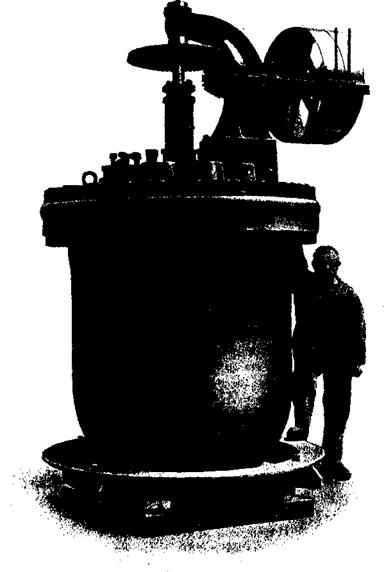
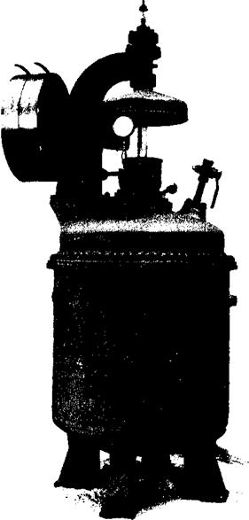
Fig. 43. Cast steel works autoclave. Capacity is 1500 liters; maximum pressure, 40 atm. The stuffing box is too close to the stirrer mount, making it difficult to install the packing. |
|
finally by using a heavy lead hammer at the end of a long wrench. In this way, there is no ganger of stripping the threads.
The autoclave itself should not come in direct contact with the materials being handled in it, since any melt will attack the walls and the apparatus will be weakened after a time. Hence, a liner is almost always installed, set in with solder. It is not feasible merely to set the liner in the autoclave since then the heat transmission is not sufficiently good. To install the liner, it is suspended rigidly from a strong cross beam and the metal is poured in through an iron funnel. Enamel and lead are protected by covering the inner side of the liner with wet cloths. It is also possible to fill the liner with water, but the water should be heated a little at the beginning and then cooled by water coils. If the water is not heated, the solder may not get completely to the bottom before it solidifies; the later cooling is necessary to prevent all of the water from boiling off.
Inadequate heat transfer can be caused not only by an air space, but to an even greater extent by salt crust formation on the inside of the vessel. Hence, mixtures from which salts separate must always be stirred, and the stirrer should come as near to the walls as possible in order to keep them free from incrustation. When large amounts of salt separate, even the best stirrers are inadequate. One case is known where a salt crust only 4 cm. thick resulted in overheating an autoclave to the point where it was red hot. At an internal temperature of 240°C. and pressure of 48 atmospheres, the autoclave was blown out like a balloon and the bottom split. The escaping gas cooled the steel enough so that no further danger was involved. It is almost certain, however, that cast iron would have exploded. (Fusions such as those in the preparation of уЗ-naphthol, if done without a metal bath, would certainly ruin any pressure vessel.)
For these reasons, it is essential, whenever possible, to place the autoclave in a heating bath. Oil or solder are used as the heating liquids. Even when no salt crusts are formed to interfere with heat transfer, phenomena occur at higher temperatures which make the use of a solder bath desirable. The solder surrounding the liner is melted if the autoclave is heated directly, and this results in the liner being lifted. Finally, the liner is pressed against the autoclave cover and, after cooling, prevents proper tightening of the cover. After a time, leaks develop, and forcing the nuts to overcome the difficulty is a source of great danger. Incorrect heating is bad not only for the autoclave but also for the compounds involved. The cases of a-naphthol and /З-naphthylamine have already been discussed in detail.
The autoclave is charged through the manhole, and this is then closed carefully, or, if possible, the material is drawn in by suction through the emptying tube. The latter procedure gives less chance for formation of leaks. Since water expands considerably when heated — about 20 per cent from 0 to 250°C. (Mendelejew) — an autoclave should not be filled to more than 80 per cent of its total capacity. If the vessel is too full, the pressure becomes so high that the autoclave will be split. A table should be posted over every autoclave, listing the total volume, maximum pressure, maximum charge, and the type of liner.
|
|
Pressure equipment is designed by engineers who have official standards upon which to base their work. It is recommended practice, nevertheless, to have each apparatus checked by a first class firm before application is made for a permit for the project.
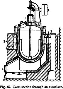
The autoclave is installed in the previously completed masonry structure by means of a traveling hoist. The walling should be reinforced by iron rods, spaced 30 cm. apart, whose protruding ends are anchored with iron plates measuring 25 by 25 cm. The autoclave or its heating bath is set on a sunken ring (seen at the bottom in Fig. 43), and the apparatus is filled and heated. If the installation has been made properly, there is no need to proceed with excessive care in this first heating, although
it is usually best to start out with a small flame. The rods of the grate should be kept free, and if necessary one or more of them should be removed in case the draft is insufficient. It is recommended that a separate chimney be used for each two large autoclaves, so that the autoclave operations are not dependent on neighboring apparatus. In general the heating period, is several hours. Once the masonry is hot, a small fire is sufficient to keep the temperature up. The radiation becomes so large at temperatures above 200°C. that the part of the autoclave extending out of the fire box must be insulated with a sheet iron cover lined with asbestos. This insulating cover is made in sections so that when the apparatus is to be cooled, the cover can be removed and the fire door and the soot door can be opened. Cooling of the autoclave can be greatly accelerated by blowing off part of the contents (into a condensing system in the case of alcohol or ammonia), and in this way the masonry does not lose much heat, which is important for the next operation. The autoclave must be watched carefully during the heating operation. The temperature of the oil bath should be about 30° higher than the inner temperature, and the two thermometers (also the two manometers) should agree with each other to within 2 scale divisions. If they show a greater difference, the thermometers should be checked, and if necessary, the operation interrupted. The operation of an autoclave can be supervised from the laboratory by means of remote-recording thermometers, and recording manometers are being used increasingly since they give records which can be checked even after the operation is completed. All observations should be recorded accurately, so that a record is available in all cases of interruption or accident. If, despite all precautions, real trouble arises, such as a sudden, unexpected increase in pressure or temperature, the fire is raked out without delay, the valve and soot door are opened, and the immediate vicinity of the autoclave is evacuated. Explosion of an autoclave, such as those shown in Figure 43 and 44, can wreck a whole plant. Since all pressure vessels are built with great care, however, no danger is involved if they are operated properly.
Every pressure vessel must be inspected officially each year, at a time when it is cooled and thoroughly cleaned out. The apparatus is entered only after it is shown that a candle burns normally inside. Usually, only the manhole is opened and the apparatus is blown out with compressed air. Two people should always work together, and the results of the inspection should be certified officially. Frequently, a gauge can be used to measure accurately any change in the walls of the vessel. The liner must be removed for inspection. The autoclave is heated until the solder is melted, and the liner is raised out with a hoist. The solder is then ladled out with an iron ladle into ingot molds.
Autoclaves are usually installed in high, light rooms equipped with traveling hoists. Figure 56 on page 376 shows, in cross section, a factory layout for a dye plant with its adjoining autoclave room. The illustration shows how the completed reaction mixture is transferred directly from the autoclave to the processing rooms.
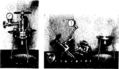
The construction of laboratory autoclaves is very similar to that of large pressure vessels. Figures 46 and 48 show two cast steel laboratory
|
Fig. 46. Cast steel laboratory autoclave with stirrer: working pressure, 60 atm.; capacity, 1 liter; weight, 33 kg.; weight of oil bath (copper), 11 kg. 1, autoclave lining; 2, stuffing box; 3, thermometer well; 4, stirrer; 5, manometer; 6, valve; 7, autoclave body with bolts; 8, copper oil bath with iron ring. |
autoclaves, and Figure 47 shows the first one in cross section. The liners must be carefully set in with lead as already mentioned. If solder is used instead of oil as a heating medium, the bath must be of iron since copper is attacked by lead. Usually, it is not necessary to cool the stuffing box on a laboratory autoclave, since only a small loss results if a leak develops. Cooling is employed only where high pressures and temperatures are involved, but, in these cases, the rotating autoclaves, described later, are to be preferred. It should be mentioned that the stirrer should rotate in the direction which will not unscrew the stuffing box nut. The cover of a laboratory autoclave is tightened carefully in exactly the same manner as described for the large equipment except that here the final
tightening by striking with a hammer is not used for fear of stripping the bolts. It is sufficient to hold the autoclave tightly and tighten the nuts as much as possible with a long wrench.
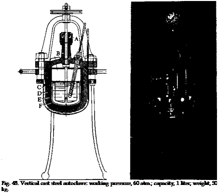
The cover of the autoclave can be either domed or flat, the latter being preferred generally, because the stirrer mount can be tightened
Fig. 47. Cross section through the laboratory autoclave shown in Figure 46. (A) stuffing box; (B) packing; (C) oil bath; (D) cast steel body; (E) lead; (F) liner.
more easily and the holes for the fittings can be packed more easily. The autoclave shown in Figure 48 has a domed cover with holes for the fittings.
Heating is done with a Fletcher burner, and later heat is applied by a good Bunsen burner placed directly under the center of the autoclave and not with several burners supplying heat to different areas. The autoclave should be protected from drafts by means of a sheet metal
shield, resulting in a saving of gas up to 70 per cent. For cooling, the whole apparatus is raised from the bath and set on an iron triangle, letting the oil drip into the bath. Heating and cooling take only about 1 hour. In case unexpected phenomena appear, the same rules are applied, with appropriate modifications, as in large scale operations. The cover bolts should not be tightened when the autoclave is under pressure, although the bolts around the stuffing box may be. General rules governing the use of autoclaves are listed later.
Instead of using an enameled liner, the inside of the autoclave body and the cover can be enameled directly, although there are but a few
|
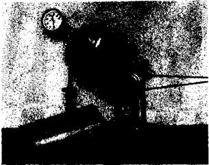
Figure 49. Rotating wrought iron autoclave with warm gear drive: weight, 11 kg; capacity, 400 cc.; working pressure, 100 atm. |
firms supplying satisfactory equipment of this type. The cost of enameling varies with the weight of the apparatus.
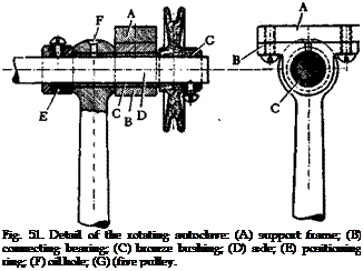
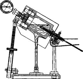
Pressure reactions with stirring are difficult to carry out in the laboratory if the pressure exceeds about 20 atmospheres because the stuffing box must be very tight and also cooled. For this reason, the rotating autoclave shown in Figures 49 and 50 has been used in this laboratory for a number of years. It is built according to well-known principles of construction, although certain innovations have bgen introduced. The opening is reduced so that fewer bolts are used, and the whole body of the autoclave is made in one piece from an old wrought iron pressure cylinder. The apparatus is set on an incline, at a variable
angle, so that both pressure and temperature can be measured, care being taken that the contents of the autoclave do not come in contact with the packing. The manometer is installed in the top opening, and the thermometer, held in place by asbestos paper, is inserted in the bottom hole. The weight of the autoclave is not carried on the worm gear shaft, but by a bronze bearing on the supporting frame (Fig. 51). With
|
Fig. 50. Cross section through the rotating autoclave. |
this arrangement, suprisingly little power is required. The apparatus weighs 11 kilograms with a charge of 400 cc. and is built for 100 atmospheres pressure. The frame weighs about an equal amount. During the heating, the cylinder is covered by a sheet metal hood, and the gas consumption is less than 20 per cent of that required with other autoclaves. Attempts to use a simple screw top closure instead of the more expensive bolt and nut arrangement were unsuccessful, because the packing, which was merely pressed against the cover when the screw closure was tightened, did not give a good seal and always blew out at about 180°C.
As shown in the sketches, the burner should be placed beneath the lower part of the autoclave which is filled with the material. In this way, overheating of the packing is avoided.
The rotating autoclave is especially suitable for handling pasty mix-
 |
|
tures or suspensions of solid materials. The mixing is often inadequate if immiscible liquid layers, differing widely in specific gravity, are formed at the reaction temperature. Some improvement is obtained by adding a few steel balls to the mixture, but it is better in these cases, if the pressure is not too high, to use a stationary stirring autoclave.
General Rules on the Use of Pressure Vessels
(1) The packing must always be clean. (2) Nuts are tightened in opposite pairs, first lightly, then increasingly tightly around the circle.
(3) If the reaction mixture is neutral and does not evolve ammonia on heating, a manometer with a bronze tube can be used. If fumes which attack copper or bmnze are generated, however, a steel tube manometer is used. Copper and bronze are corroded very rapidly. (4) A liner should always be used, and the solder between the liner and the autoclave body must be replaced whenever it is forced out. Only under very special conditions can the liner be dispensed with. (5) The temperature of the oil bath (or metal bath) and the internal temperature should be measured. The external temperature is about 25° higher. (6) The autoclave must be protected from drafts. To this end, it is insulated and, in larger installations, covered with a shield. (7) The reaction must be interrupted
if the vessel develops a leak. The nuts should not be tightened as long as the vessel is under pressure. The stuffing box nuts can be tightened during operation. (8) The autoclave should be opened only after the valve has been opened since the manometer may frequently not indicate residual pressure in the apparatus. (9) The oil bath and the autoclave itself should never be completely filled. Water and oil expand greatly on heating, and if the autoclave is filled completely, it will be cracked. (10) Every pressure vessel should be inspected officially once a year, and a certificate issued stating the results of the inspection. The date of the inspection is stamped on the vessel along with the capacity and maximum pressure. (11) Industrial autoclaves should be cleaned thoroughly, cooled, and equipped with an air hose before inspection. (12) The properly reinforced masonry for an industrial autoclave is prepared in advance, ahd the completely assembled autoclave, in working order, is set into it.
 28 декабря, 2015
  Pokraskin
 Опубликовано в рубрике