With few exceptions, all constructions, components and their joints are generally exposed to long-term static or alternating loads rather than short-term loads. For example, over the whole operating life of a car (around 12 years), the coil springs and their fastening elements must carry part of the car’s weight without undue plastic deformation, and they must resist, without damage, dynamic states of stress produced during service over a total period of approximately 3000 h (corresponding to about 150 000 km distance covered). A reliable dimensioning of these components is possible by using material parameters determined under conditions at least similar to those met in service. With regards to adhesive bonds, the viscoelastic-plastic behavior ofthe adhesives must be translated into material parameters which, ideally, are reflected by isochronous shear stress-shear strain diagrams for given temperatures, and where each measuring point characterizes the shear stress-shear strain behavior of a given adhesive under long-term static or even dynamic load. With few exceptions, however, such diagrams are not available as they require an enormous testing effort. Another, easier testing method is therefore preferable. The simplest method would be to expose tensile lap shear specimens to different static or alternating mechanical loads, and to determine the time taken to rupture under static loading, or alternatively the number of loadings supported by the specimen until rupture of the joint (i. e. fatigue strength; see Section 7.3.3). Some typical results of these tests are shown in Figures 7.31 and 7.32. Up to a temperature of 40 °C, the phenolic resin adhesive supported up to 70% of its static failure load when exposed to long-term static loading. At 80 °C — that is, above its Tg-value — it was hardly loadable any more when exposed to long-term loading. The cold-setting epoxy resin could only be loaded with up to 50% of its short-term load capacity when exposed to long-term loading (up to a maximum of 60 °C; above this temperature, the time to rupture could no longer be measured).
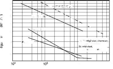
Like the time to rupture, the fatigue strength of assemblies joined with a given adhesive depends on the adherent material (and its surface condition). Experience has taught us that numbers of stress cycles in excess of 106 induce a flattening of the Wohler diagram, reflecting a form of fatigue limit. In this respect, the fatigue strength is approximately 15-20% of the short-term load capacity. This has to be put into perspective, however, as the fatigue strength of bonded joints also depends on the loading rate (Figure 7.33). This can be explained, on the one
|
Figure 7.31 Time to rupture of bonded aluminum under static loading as a function of temperature. Adhesives: upper, phenolic resin; lower, cold-setting two-part epoxy resin. |
hand, by the fact that at a low load frequency, testing until rupture takes considerably more time than at a high frequency. On the other hand, due to the viscoelastic-plastic behavior of the adhesives, the damage process is probably different when the specimen is exposed to short-term stress cycles (i. e. to a higher load frequency) as compared to a low frequency. Evidence suggests that, at very high loading frequencies, the loss in strength practically no longer depends on the number of stress cycles, although this behavior has not yet been systematically investigated.
In summary, the time to rupture ofadhesive bonds under static load can cautiously be estimated to be 50-70% of its static failure load, and their fatigue strength can be estimated at around 15-20% of their short-term load capacity. As will be illustrated in Section 7.7.5 (the durability of adhesive bonds), in the majority of applications the mechanical load capacity of adhesive bonds is suitably described by the parameters determined under tensile shear loading.
 |
 7.7.3
7.7.3
Peel Strength
The peel strength of adhesive bonds can be determined using several test methods (see Section 7.2). This reflects the resistance of the bond-line to peel forces produced by a load that is applied eccentrically and perpendicular to the bond-line. Both, the crack initiation resistance and resistance to crack propagation within the bondline are measured. The peel resistance depends not only on the properties of the adhesive used but also on the geometry, the surface conditions, and the material of the adherents, particularly on their deformation behavior, as well as on the rate of peeling. Therefore, a peel strength that was determined with a given adhesive bond configuration may not necessarily be applied to others. Rather, qualitative data are
 |
|
only provided for the purpose of comparison, for example in a test run where only one testing parameter is changed, and all other parameters are maintained.
The peel strength characteristics of a PSA are shown in Figure 7.34 (its tensile shear strength as a function of the crosslinking rate is illustrated in Figure 7.28). The tensile shear strength of this PSA increases with increasing crosslinking rate, whereas the peel resistance decreases. In peel tests, the deformation behavior of an adhesive is tested rather than its strength. The complicated peel behavior of adhesives, and its causes, will not be discussed in detail here [13]. In principle, peel tests are fracture-mechanical methods which involve testing conditions that are hardly suitable in terms of fracture mechanics; hence, they provide only qualitative data for comparative purposes. However, in this case the peel tests are perfectly valid, especially when the results are considered within the context of strength data, as in the above-mentioned example.
Well-plasticized structural adhesives can have a maximum peel strength (see Section 7.2.6) of approximately 20 N mm-1, with similar values being obtained when using completely different systems and geometries.
In former times, peel strength was an important factor that had to be considered when deciding in favor of, or against, bonding. This was especially the case when formulating high-strength adhesives, as a high load capacity could not be combined satisfactorily with high peel strength. Today, however, this problem has been largely solved.
7.7.4
 28 октября, 2015
  Pokraskin
 Опубликовано в рубрике